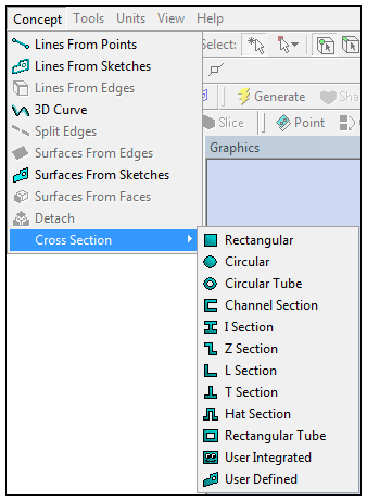
The Cross Section menu is accessible via the Concept Menu in the DesignModeler Menus toolbar.

Cross sections are attributes assigned to line bodies to define beam properties in the Mechanical application. In Ansys DesignModeler, cross sections are represented by sketches and are controlled by a set of dimensions. You may only modify the dimension values and dimension locations of a cross section; they are not to be edited in any other way. The 12 cross section types supported in DesignModeler correspond directly to specialized beam section types used in the Mechanical APDL application.
Note: The cross section calculation in DesignModeler is based on facets, which may cause the values of section properties in DesignModeler to differ from the values of section properties calculated at the solver level. For example, the values calculated for moments of inertia are approximations. They will typically be within 2% of the actual value. These reported values in DesignModeler have no bearing on the simulation.
Cross Section topics:
| Coordinate Systems for Cross Sections |
| Editing Cross Sections |
| Cross Section Assignment |
| Cross Section Offset |
| Cross Section Alignment |
| Cross Section Inheritance |
| Cross Section Types |
| Deleting Cross Sections |
Other Concept Menu feature options:


