


The Icepak system launches Ansys Icepak. This application allows engineers to model electronic designs and perform heat transfer and fluid flow simulations. You can construct your model geometry or import model data from other CAD and CAE packages. Icepak then creates a mesh for your model geometry and passes the mesh and model definition to the solver for computational fluid dynamics simulation. The resulting data can then be postprocessed using Icepak and/or CFD-Post.
Workbench has the capability of coupling Ansoft steady-state to Icepak steady-state cases and Ansoft transient to Icepak steady-state cases.
To work through an Icepak system:
To add an Icepak component system, drag the system from the Toolbox to the Project Schematic or double-click the system in the Toolbox.
Right-click the Setup cell and select Edit or double-click the Setup cell. This launches Icepak.
Create a geometry within the Icepak application.
After creating a geometry, the system displays the cell state as Unfulfilled.

The Update Required icon (
 ) indicates the system has not
been solved.
) indicates the system has not
been solved.In Icepak, set up the problem and complete your analysis using Icepak's tools and features.
After solving, the Icepak system displays an up to date cell state as shown below.
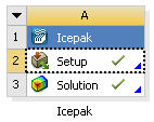
The Up to Date icon (
 ) indicates that
all necessary files are loaded and up to date.
) indicates that
all necessary files are loaded and up to date.Load or import an existing Icepak model by selecting one of the following options:
To load an existing Icepak model, right-click the Setup cell and select Import Icepak Project.
To import an existing Icepak model:
Right-click the Setup cell and select Import Icepak Project From .tzr.
Click Browse
In the dialog box, browse the directory structure and select the model to load.
The system displays an incomplete cell state.
The Update Required icon (
) indicates the
system has not been solved.
Icepak project files are located in the system directory under IPK. All Icepak projects saved in Workbench follow this naming convention which is described in Project Directories. All other Icepak projects can be saved anywhere. Note, there are no special icons for Icepak projects to differentiate them from other files.
Note: You can only import one Icepak project per system.
In Icepak, set up the problem and complete your analysis using Icepak's tools and features.
After solving, the Icepak system displays an up to date cell state as shown below.
The Up to Date icon (
) indicates that
all necessary files are loaded and up to date.Note: If you load an Icepak project that already has a solution, the Solution cell state will show an up to date cell state after the model is loaded.
You can also import geometry into Icepak from DesignModeler. See the DesignModeler to Icepak section for details on importing geometry from DesignModeler into Icepak or loading a geometry.
Many Icepak options remain the same when running Icepak from the Workbench framework. However, there are a few changes that should be noted.
| Menu Item | Description |
|---|---|
| Save project | Saves all changes to your project. The Save button in Workbench works the same way as Save project in Icepak, you can use either one. All Icepak projects saved in Workbench will follow the directory structure described in Project Directories. See Saving a Project File for a description of Save and Save as options in Workbench. |
| Archive | Generate a single archive file that contains all project files.
This archive includes the project file and all files in the
project_name_files directory, not just
Icepak files. The archive is saved as a zip file. Icepak users
familiar with the Pack option in the standalone Icepak application
will find this option works in a similar fashion except that all
Workbench files are archived. See Archiving a Project
for a complete description of the Archive
option in Workbench. Note: Previously imported external files from a restored archive directory are treated as internal files if archived again. |
Icepak Context Menu Options
When the Icepak system is active in the Project Schematic, use the right mouse button to initiate the following Setup cell actions.
| Menu Item | Description |
|---|---|
| Edit | Launches Icepak. This is the default operation. |
| Import Icepak Project From .tzr | Opens a Browse dialog box to add an input file, then launches Icepak and reads the input files. This is the default action. This option is available only when a project is empty. |
| Import Icepak Project | Opens a Browse For Folder dialog box to add an input file, then launches Icepak and reads the input files. This is the default action. This option is available only when a project is empty. |
| Duplicate | Creates a duplicate of the Icepak system and any upstream data. If the duplicate operation is performed on a system containing a solution, the solution is transferred and you must re-solve. The system cell state indicates the need to re-solve. |
| Transfer Data From New | Creates a second, dependent (connected) system with the existing system. |
| Update | Updates the system if data is changed or modified. You have the
option to incorporate the changes in the Refresh Input
Data pane and initiating the solver inside Icepak.
See DesignModeler to Icepak for
a further description of the update option and how the
Refresh Input Data panel is used. Note: You must open the Icepak editor before doing an update. |
| Refresh | Refreshes the system if data is changed or modified. You have the
option to incorporate the changes in the Refresh Input
Data panel. See DesignModeler to Icepak for a further description of the
refresh option and how the Refresh Input Data
panel is used. Note: You must open the Icepak editor before doing a refresh. |
| Rename | Renames the system or cell. |
| Properties | Displays applicable cell properties in the Properties pane. |
| Enable Update | Allows you to run the solution if data is unchanged. This changes the Setup cell icon from a green check mark to the Update lightning icon. |
| Quick Help | Displays a quick help panel for the cell. Quick help provides a brief description of how to use the cell in its current state. You can also click the blue triangle in the lower right corner of a cell to view quick help. |
The Solution cell actions are similar to those of the Setup cell; however, there are additional actions and functions. These are described in the list below. Use the right mouse button to initiate the following Solution cell actions.
| Menu Item | Description |
|---|---|
| Set Case File... | Opens an Open dialog box where you can specify an Icepak solution file to load. This option is used primarily to view multiple solutions for a project. If the you re-solve in Icepak, the solution case file is overwritten with the latest solution. |
| Transfer Data to New | Creates a downstream system that can accept data from the selected cell. Only those systems that can provide valid data to the selected cell are shown. When you select a system from the options shown here, that system is displayed to the right of the currently-selected system, with all appropriate connections drawn. |
| Update | Performs an update if solution data is changed or modified. You can bring in the latest solution case file into the solution cell for consumption. |
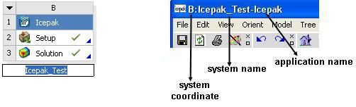
System Names
You can enter an Icepak system name for your project as described in Naming Systems. In addition, you can use the Rename option to change the name of a system or cell. In the Icepak application, the system coordinate, system name, and application name are displayed in the top left corner.
Icepak Properties
Select or enable Use Workbench Color Scheme to keep the Workbench background graphics colors and display defaults in Icepak.
To enable this option:
Right-click the Setup cell and select from the context menu.
In the Value column, select the Use Workbench Color Scheme check box.
CAD models created or edited in DesignModeler can be imported into Icepak. Icepak instructs DesignModeler to export the current DesignModeler geometry into Step file format so it is readable by Icepak.
To transfer geometry upstream to Icepak:
To add a Geometry component system, drag the system from the Toolbox to the Project Schematic or double-click the system in the Toolbox.
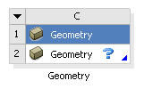
The Attention Required icon (
 ) indicates that an input
file is required.
) indicates that an input
file is required.
To launch the DesignModeler application, double-click the Geometry cell or right-click the Geometry cell and select New Geometry from the context menu.
You can import any geometry or load an existing DesignModeler geometry by right-clicking the Geometry cell and selecting Import Geometry from the context menu.
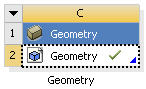
The Up to Date icon (
)
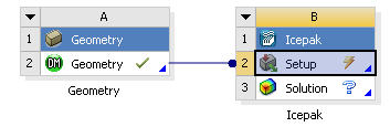
indicates that all necessary files are loaded and up to date.Establish the connection to Icepak using one of the following options:
Drag and drop an Icepak system on top of the Geometry cell.
In the Toolbox, double-click Icepak to add the Icepak system to the Project Schematic, then click the Geometry cell and drag it to the Icepak Setup cell.
Right-click the Geometry cell and select from the context menu, then select a system that uses DesignModeler.
Right-click the Geometry cell and select from the context menu, then select a connection to Icepak.

To launch the Icepak application, double-click the Setup cell.
If the geometry is different from DesignModeler’s native format (.agdb), you must edit the geometry first before exporting into Icepak.
A new project is created and DesignModeler geometry is imported into Icepak as STEP geometry.
If the geometry has been modified, refresh the Icepak Setup cell to bring in the new geometry.
After you refresh the data, you must either replace the entire model in Icepak or update individual geometries that have changed. You are prompted with the following dialog box.
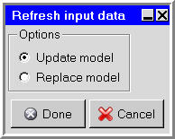
If you select Update model, the Icepak model is updated to match the existing model in DesignModeler which may result in creating objects that are not currently present in the Icepak model, the geometries of modified objects will be updated, and the thermal and material properties of the updated objects are retained. Objects created separately in Icepak will not be updated.
If you select Replace model, the entire Icepak model will be replaced with the latest input CAD data from DesignModeler.
See the sample session in Chapter 2 of the Icepak documentation for an example on how to use Icepak. See Understanding Cell States for a complete list of all cell states.
Perform an analysis on the model if you have not yet done so.
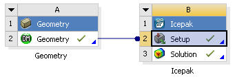
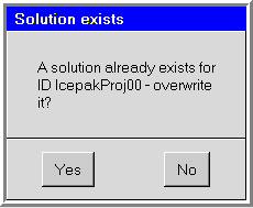
If the geometry has changed after you have solved, update the Solution cell to bring in the new changes.

You can choose to not overwrite the solution using the dialog box shown below, and the update is cancelled (
 ).
).
Note: See Workbench Menu Options Overview for Icepak Projects for information on how to save your project.
Icepak provides two methods for examining the results of your simulation; you can postprocess results inside of Icepak or by using CFD-Post.
To postprocess results in Icepak, add an Icepak system to the Project Schematic and perform an analysis on the model. You can then create graphical displays and examine your results in Icepak. For details, see Examining the Results in the Icepak User's Guide
To postprocess Icepak results in CFD-Post:
Connect the Icepak system to a CFD-Post Results system using one of the following options:
Drag and drop a Results system on top of the Icepak Solution cell.
In the Toolbox, double-click Results to add the Results system to the Project Schematic, then click the Icepak Solution cell and drag it to the Results cell.
Right-click the Results cell and select from the context menu, then select the Icepak system.
Right-click the Geometry cell and select from the context menu, then select the Results system.
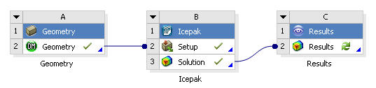
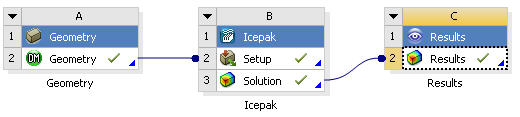
Icepak results can be postprocessed in CFD Post by double-clicking the Results cell. If you have more than one solution or your solution has changed, you need to update the Results cell. If solution data is not transferred, then Results cannot be launched. See CFD-Post help for more details.
Icepak results can be transferred to the following analysis types within Workbench: Static Structural, Steady-State Thermal, Transient Structural, or Transient Thermal.
To add an analysis type:
Add an Icepak system to the Project Schematic and perform an analysis on the model inside Icepak.
Connect the Icepak system to a Mechanical system using one of the following options.
Drag and drop an Analysis cell on top of the Icepak Solution cell.
In the Toolbox, double-click a Mechanical analysis system to add it to the Project Schematic, then click the Icepak Solution cell and drag it to the analysis Setup cell.
Right-click the analysis Setup cell and select from the context menu, then select the Icepak system.
Right-click the Icepak Solution cell and select from the context menu, then select a Mechanical analysis system.
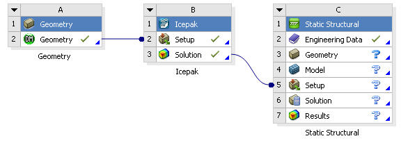
Load geometry to satisfy the system.
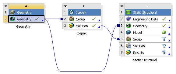
Double-click the Setup cell to launch Mechanical.
While in Mechanical insert the appropriate loads based on the type of analysis. See Icepak to Mechanical Data Transfer for a detailed description of how to import an external load.
The exploration of a given design can be performed by using optimization algorithms in Ansys DesignXplorer. Parameters exposed from Icepak provide a method for solving an optimization and/or parameterization problem.
To publish Icepak variables:
In Icepak, define input and output parameters. See Overview of Parameterization for a description on how to define parameters.
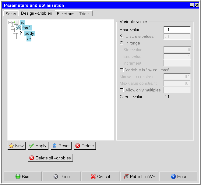
Note: The Design variables tab of the Parameters and optimization panel displays all the parameters names that are currently defined, along with their associated values.
In the Setup tab of the Parameters and optimization panel, select Single trial (current values) for Trial type if not already selected.
At the bottom of the Parameters and optimization panel, click to display the Publish to WB panel.
In the Publish to WB panel, select the input and output variables to publish to Workbench.
Note: Variables can be selected independently. In the case of multiple variables, click the green check mark to toggle all variables on and off.
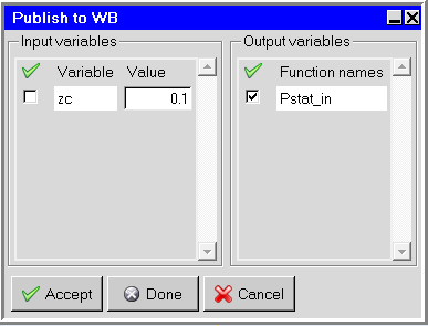
Click Accept to publish variables to Workbench, click Done to publish variables and close the panel, or click Cancel to withdraw the request.
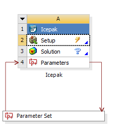
Workbench recognizes the parameters defined and exposes them in a parameter set bar that can be shared by multiple systems.
To access the Parameters tab, double-click the parameter bar or right-click and select Edit from the context menu.
For information on defining parameters, refer to Working with Parameters and Design Points.
Important: You cannot create, edit, delete, or rename parameters in Icepak if any iterations (or time-steps) have been performed. If you want to create, edit, delete, or rename parameters in Icepak for a case with an existing solution, you must first initialize the solution.
To create a new design point, either duplicate an existing design point or add a new one by entering values.
Important: Only the data from the design point in the row labeled Current is saved with the project. If you want to postprocess the results from a different design point in either Ansys Icepak or Ansys CFD-Post, click the box in the Exported column for that design point before you update that design point. Otherwise, the data for that design point is automatically deleted after the output parameters for that design point are updated. If you choose to export a design point, the data associated with that design point is exported to a new project. The new project is located in the same directory as the original project. The name of the project is the same as the name of the original project, except that it is appended with _dpn, where n is the row number that corresponds to the design point in the original project’s Table of Design Points.
Optimization of an Icepak system can be performed in Ansys DesignXplorer. Ansys DesignXplorer provides various optimization methods with parameters as its fundamental components. These parameters can come from any supported analysis system, such as Icepak, DesignModeler, and various CAD systems. Responses can be studied, quantified and graphed. For information on how to set up an Ansys DesignXplorer analysis, see the DesignXplorer User's Guide.
Icepak can be coupled with Ansoft applications within Workbench in order to perform a one-way or two-way electromagnetic-thermal interaction problem. Coupling between Ansoft and Icepak applications within Workbench can be used for simulating fluid flow around or inside electromechanical (EM) devices when the temperature of the device is influenced by electromagnetic losses.
The coupling involves solving an electromagnetic problem in the Ansoft application, and mapping the resulting volumetric heat loss and/or surface loss information into Icepak. Volumetric loss is mapped onto the solid cell zones as a heat source (load) at the cell centroids that is then added to the energy equation. Surface loss is applied to the adjacent cells of the solid zones at the surface that contribute to the source terms of these cells.
Note: Surface loss is highly concentrated near the surface of the solid zone, so you should have a fine layer of good quality hexahedral or prism mesh elements located where surface loss occurs.
You can analyze the results of volumetric or surface losses using the heat flow postprocessing variable under Summary report.
When surface losses are enabled, the double precision solver is recommended.
One-way Coupling between Ansoft and Icepak Within Workbench
To work through an Icepak- HFSS/Maxwell/Q3D Extractor analysis:
Connect Ansoft to Icepak using one of the following options:
Add a HFSS/Maxwell/Q3D Extractor system to the Project Schematic.
To add a HFSS/Maxwell/Q3D Extractor system, drag the system from the Toolbox to the Project Schematic or double-click the system in the Toolbox.
Import/create the geometry in the Ansoft application.
Set up the problem and solve to obtain a solution for transfer into an Icepak system.
Connect the HFSS/Maxwell/Q3D Extractor Solution cell to the Icepak Setup cell.
Transfer data from the Icepak system:
On the Icepak system, right-click the Solution cell and select from the context menu.
Select a connection to a HFSS/Maxwell/Q3D Extractor system.
Transfer data to an Icepak system:
On the Geometry system, right-click the Geometry cell and select from the context menu.
Select the Icepak system.

To launch the Icepak application, double-click the Icepak cell.
A new project is created in the name of the project cell. If a DesignModeler system is used the geometry is imported into Icepak automatically. Otherwise, the geometry must be created in Icepak using Icepak primitive objects.
Note: The geometry can be exported from the HFSS/Maxwell/Q3D Extractor cell to a Geometry cell and imported to the Icepak cell using DesignModeler Electronics.
In Icepak, go to the File menu and select EM Mapping and Volumetric heat losses or Surface heat losses.
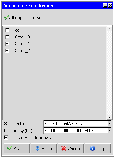
The Volumetric heat losses panel contains the following inputs:
A list of solid objects onto which the loss information can be mapped. For these objects, Icepak requests the heat source (loss) terms from the Ansoft application. Click the Objects button to toggle your current object selections. Right-click Objects and select All or None to select all or none of the objects.
Solution ID contains available solution sets. Since the HFSS/Maxwell/Q3D Extractor application may have multiple solutions, Icepak requests the generated heat source data for the selected solution.
Frequency (steady-state only) contains available frequencies. Icepak will request that the HFSS/Maxwell/Q3D Extractor application provide the heat source data for the selected frequency.
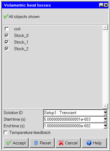
Start time(s) and End time(s) (transient only) contains the available time steps. Icepak will request that the HFSS/Maxwell/Q3D Extractor application provide an averaged heat loss for the selected time steps.
Note: The Start time(s) and End time(s) specified are applied to both volumetric and surface heat losses.
Temperature feedback option is used in two-way coupling problems. This option is explained below.
Click Accept to close the panel.
In Icepak, click Start solution to solve the project.
During solving, HFSS/Maxwell/Q3D Extractor is launched in the background and the volumetric losses calculated and mapped onto the selected Icepak solid objects. This loss mapping from HFSS to Icepak is conservative. This is especially important for accurate temperature calculation.
Two-Way Coupling Between Ansoft and Icepak Within Workbench
Two-way coupling enables thermal feedback to be provided between the systems so that you can exchange temperature data from Icepak to Ansoft applications within Workbench.
To enable two-way coupling between Icepak and Ansoft:
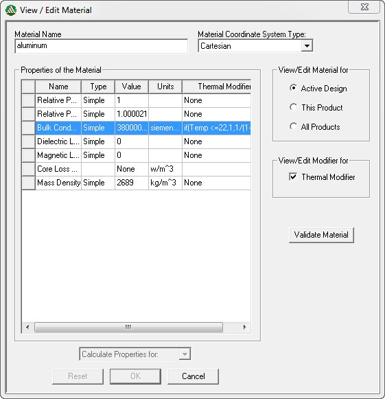
Open the Maxwell (or HFSS/Q3D Extractor) project and define temperature–dependent material properties (enabling the Thermal Modifier field in the View/Edit Material dialog box and editing the material’s thermal property definition).
This makes sure that the Ansoft and Icepak applications generate the temperature–dependent data.
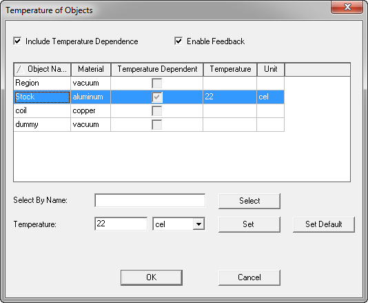
In the Temperature of Objects dialog box, select Enable Feedback.
The Temperature of Objects dialog box is displayed when selecting Set Object Temperature in the Maxwell 3D /HFSS/Q3D Extractor menu.
Note: In Maxwell/HFSS/Q3D Extractor, you can have different losses (Ohmic loss, Core loss, Hysteresis loss) depending on the type of simulation. Maxwell/HFSS/Q3D Extractor can also compute the "total loss" which is the sum of all the losses when appropriate. All the different losses mentioned above including the "total loss" are a function of space and they are also a function of time in the Maxwell/HFSS/Q3D Extractor transient solver. When doing the coupling simulation, the "total loss" is mapped to Icepak for the temperature calculation. For transient simulations, the total loss is time averaged between two times that you specify before it is mapped to Icepak.
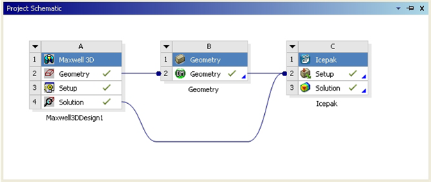
Connect Ansoft to Icepak using one of the following options:
Transfer data from the Icepak system:
On the Icepak system, right-click the Solution cell and select from the context menu.
Select a connection to a HFSS/Maxwell/Q3D Extractor system.
Transfer data to an Icepak system:
On the Geometry system, right-click the Geometry cell and select from the context menu.
Select the Icepak system.
To launch the Icepak application, double-click the Icepak cell.
A new project is created in the name of the project cell. If a DesignModeler system is used the geometry is imported into Icepak automatically. Otherwise, the geometry must be created in Icepak using Icepak primitive objects.
Note: The geometry can be exported from the HFSS/Maxwell/Q3D Extractor cell to a Geometry cell and imported to the Icepak cell using DesignModeler Electronics.
In Icepak, go to the File menu and select EM Mapping and Volumetric heat losses or Surface heat losses.
The Volumetric heat losses panel contains the following inputs:
A list of solid objects onto which the loss information can be mapped. For these objects, Icepak requests the heat source (loss) terms from the Ansoft application.
Solution ID contains available solution sets. Since the HFSS/Maxwell/Q3D Extractor application may have multiple solutions, Icepak will request the generated heat source data for the selected solution.
Frequency contains available frequencies. Icepak will request that the HFSS/Maxwell/Q3D Extractor application provide the heat source data for the selected frequency.
Temperature feedback enables the writing of temperature data by the Icepak solver to be sent to the Ansoft application to perform two-way coupling. This option must be enabled for two-way coupling.
Note: When volumetric heat losses are not available, two-way coupling can still be performed for surface heat losses by enabling the Temperature feedback option in the Volumetric heat losses panel.
Click Accept to close the panel.
After solving in Icepak, to send temperature data back to the Ansoft application to solve again, right-click the Ansoft application’s Solution cell and select from the context menu.
Solve Icepak again using this newly generated data. This process can go on indefinitely until you are satisfied with the results.
You can also perform manual cyclic updates of individual system components until the solution stops changing within a desired level of tolerance. For example:
Coupling Iteration 1
Update Maxwell/HFSS/Q3D Extractor Solution cell
Perform EM Mapping on solid zones in Icepak
Update Icepak Solution cell
Perform Enable update on Maxwell/HFSS/Q3D Extractor Solution cell
Update Maxwell/HFSS/Q3D Extractor Solution cell
Coupling Iteration 2
Update Icepak Setup cell
Update Icepak Solution cell
Perform Enable update on Maxwell/HFSS/Q3D Extractor Solution cell
Update Maxwell/HFSS/Q3D Extractor Solution cell
Coupling Iteration 3
Update Icepak Setup cell
Update Icepak Solution cell
Perform Enable update on Maxwell/HFSS/Q3D Extractor Solution cell
Update Maxwell/HFSS/Q3D Extractor Solution cell
Coupling Iteration 4
Update Icepak Setup cell
Update Icepak Solution cell
Perform Enable update on Maxwell/HFSS/Q3D Extractor Solution cell
Update Maxwell/HFSS/Q3D Extractor Solution cell
and so on.
You can perform automatic system updates (coupling iterations) using the Ansoft Feedback Iterator. Refer to Ansoft help documentation for more information on Feedback Iterator.
To access the Ansys Icepak - Ansys Workbench integration tutorial, go to http://support.ansys.com/training and download the Ansys Icepak Tutorial Guide.