The Injection Molding Data system allows you to take the data from result-files of injection molding simulations and import it into a Mechanical system. Supported analysis types include Static and Transient Structural; Steady-State and Transient Thermal; Modal and Harmonic Response. File formats of the most popular injection molding software tools are supported. The following quantities can be imported:
Residual stresses (before ejection)
Weld lines
Fiber orientation tensor (for reinforced materials)
Fiber volume fraction (for reinforced materials)
The input data is parsed, processed, and then transferred to a downstream Mechanical system where it can be applied in the form of element orientations, material fields, and initial stresses.
When simulating the thermo-mechanical behavior of short fiber reinforced composites, the Injection Molding Data system allows you to import injection molding simulation results from other software tools. It's part of a streamlined workflow in Workbench which also employs Material Designer and Mechanical. You will find detailed instructions and a sample workflow in the Short Fiber Composites Guide.
In the table below, you will find a list of software tools, their file-types, and whether they are supported.
| Mesh File Format | Fiber Orientation Tensor File Format | Initial Stress File Format | Fiber Volume Fraction File Format | Weld Lines File Format | |
| Autodesk Moldflow[a] | Patran Neutral file (.pat) or CDB (generated when exporting initial stresses) |
For 3D Meshes:
For Midplane meshes:
| .ist (only for 3D meshes)[b] | Not supported | .xml, .nod |
| Moldex3D | .cdb, .ans | .o2d | .ist | .fcd | .nwd |
| SigmaSoft[c] | .ans, .sac | .ans, .sac | .sac | .sac | Not supported |
| Cadmould[c] | .cof | .cof | Not supported | Not supported | Not supported |
| 3DTimon[d] | .cdb | .xml | .xml | Not supported | .xml |
[a] Only the 3D and Midplane mesh options are supported. Dual Domain meshes are not supported.
[b] Importing an .ist file in combination with the Patran mesh format is only valid for data in SI units.
[c] To import results from SigmaSoft and Cadmould, you must specify the same file as the Mesh and Fiber Orientation Tensor File.
[d] You must specify the same file as the Fiber Orientation Tensor File, Initial Stress File, and Weld Lines File.
To import injection molding simulation results, do the following:
Drag and drop an Injection Molding Data system onto the project schematic. The Injection Molding Data System is available under the Component systems group of the Workbench application.
Right-click the Setup cell and select Edit (see A, below) to display the Injection Molding Data properties (B, below). Alternatively, right-click the cell and select Properties.
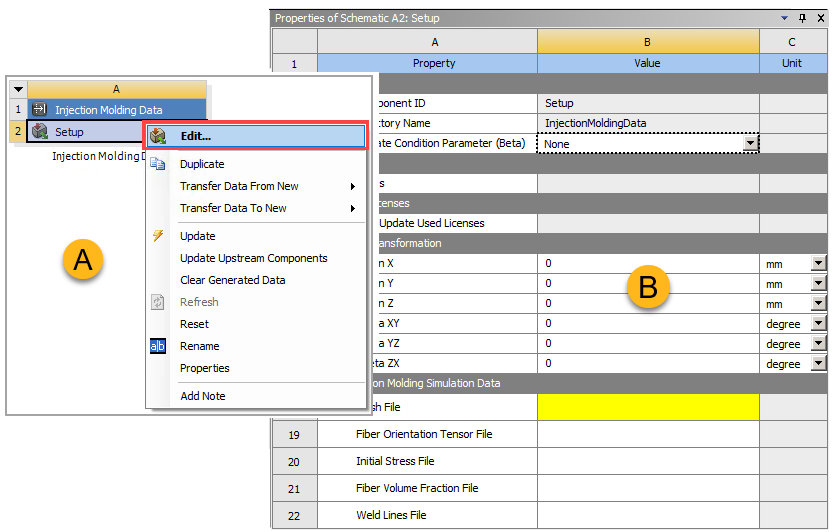
Browse to and select the location of the Mesh File.
Optional: Browse to and add the Fiber Orientation Tensor File.
Optional: Specify the location of the Initial Stress File.
Optional: Specify the location of the Fiber Volume Fraction File.
Optional: Specify the location of the Weld Lines File.
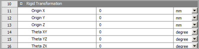
If needed, apply a Rigid Transformation to the input data by specifying the translation and/or rotation components. Transformations are applied in the following order:
Rotation about the Y Axis (Theta ZX)
Rotation about the X Axis (Theta YZ)
Rotation about the Z Axis (Theta XY)
Translations
Because of the order of rotations, the angles Theta XY/YZ/ZX can be considered as intrinsic ZXY Euler angles.
Connect to Mechanical:
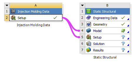
To transfer fiber orientation tensor, volume fraction, and weld lines data to Mechanical, drag the Setup cell of the Injection Molding Data system and drop it onto the Model cell of a Mechanical system.
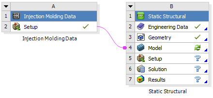
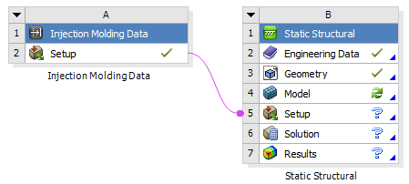
To transfer initial stress data to Mechanical, drag the Setup cell of the Injection Molding Data system and drop it onto the Setup cell of a Mechanical System.
You can combine the two transfers by right-clicking the Setup cell of the Injection Molding Data cell and choosing in the context menu.