Output parameter values for a design point are calculated when you update the design point. You can update only the current design point, a set of selected design points, or all design points. Updating design points updates solution data only where output parameters have been defined.
You have several options for updating design points. The settings specified by the Design Point Initialization property apply. For more information, see Specifying the Initialization Conditions for a Design Point Update.
When you update multiple design points, you can choose the order in which design points update. You can also choose the initial conditions with which they update.
You may want to specify the order for design point updates to improve efficiency. For instance, if several design points use the same geometry parameter values, it is more efficient to process them together so as to update the geometry only once.
By default, when each design point is updated, the design point is initialized with the data of the design point designated as current. Retained design points with valid retained data are exceptions because they do not require initialization data. In some cases, it may be more efficient to update each design point starting from the data of the previously updated design point, rather than restarting from current design point each time.
To update design points in Remote Solve Manager (RSM), see Updating Design Points in Remote Solve Manager.
Non-parametric changes made to a project with up-to-date design points may cause all existing design points to go out-of-date, if the change is related to the parametric study being performed. Any change not relevant to the parametric study, such as adding a standalone system or making a change downstream of the study, should not cause design points to go out-of-date. For changes that invalidate the design points table, you must update the project, which can require significant time and computing resources. You should always save your project after updating all design points and before further modifying the project.
In most cases, a design point update applies only to cells affected by parameter changes and to cells downstream. Cells without associated parameters or cells whose associated parameters did not change are not updated.
Related topics:
- Setting the Design Point Update Option
- Updating Only the Current Design Point
- Updating Selected Design Points
- Update All Design Points
- Fixing an Interrupted Design Point Update
- Changing the Design Point Update Order
- Specifying the Initialization Conditions for a Design Point Update
- Setting Systems using CFD-Post to Update with Design Points
Before updating design points, you must set the location where the updates are processed.
To set the design point update option:
On the Project Schematic, right-click the Parameter Set bar and select from the context menu.
In the Properties pane, from the Update Option drop-down list, select from the following options:
: Runs the design point update within the current Workbench session. This option is appropriate for quick-running updates that fit within the resources of your workstation. This option is also the most robust as it is not possible to make changes that impact the design points. When a design point update is executing in the foreground, you cannot change or save the project, but you can interrupt or stop the update.
: Runs the design point update in the background by submitting it to RSM using HPC shared licensing features.
Use this option for long-running updates that do not fit within your workstation's resources. When you submit an update, RSM can send it to a remote compute cluster or to a Cloud portal. RSM can also submit jobs to the local machine to allow the queuing of updates on your workstation.
For more information on submitting design point updates to RSM, see Updating Design Points in Remote Solve Manager.
To update just the current design point, update the project.
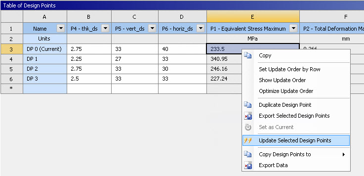
You can choose a set of design points from the table to update.
To update selected design points:
To open the Table pane, double-click the Parameters cell of a system or the Parameter Set bar.
Press Ctrl and click each design point in the table to update.
Right-click the selection and select from the context menu.

If the update for one of the design points fails, the Update Failed,
Update Required ( ) icon is displayed for the
failed design point, but the next design point update begins immediately. The
Messages pane opens, showing the error message for the
one or more design points that failed. When the update process is complete, a
failure summary dialog box opens. Review the error messages for details on which
design points failed to update.
You can update all design points in the table.
To update all design points:
To open the Table pane, double-click the Parameters cell of a system or the Parameter Set bar.
To update the design points:
From the menu bar select > .
On the Project tab toolbar click .
Right-click the white space on the Project Schematic and select from the context menu.
If the update for one of the design points fails, the Update Failed,
Update Required ( ) icon is displayed for the
failed design point, but the next design point update begins immediately. The
Messages pane opens, showing the error message for the
one or more design points that failed. When the update process is complete, a
failure summary dialog box opens. Review the error messages for details on which
design points failed to update.
If the update of a design point is interrupted, the partially updated icon
(![]() ) is
displayed beside the values of the output parameters for the interrupted
component. The next time that this design point is selected for update, a dialog
box opens.
) is
displayed beside the values of the output parameters for the interrupted
component. The next time that this design point is selected for update, a dialog
box opens.
To continue, select from the following options:
: Accepts output parameters that are only partially updated as up-to-date, using the existing results to update design points.
: Restarts the interrupted update, recalculating results for all output parameters that are partially updated and then updating all design points. The dialog box notes that this can be a lengthy process.
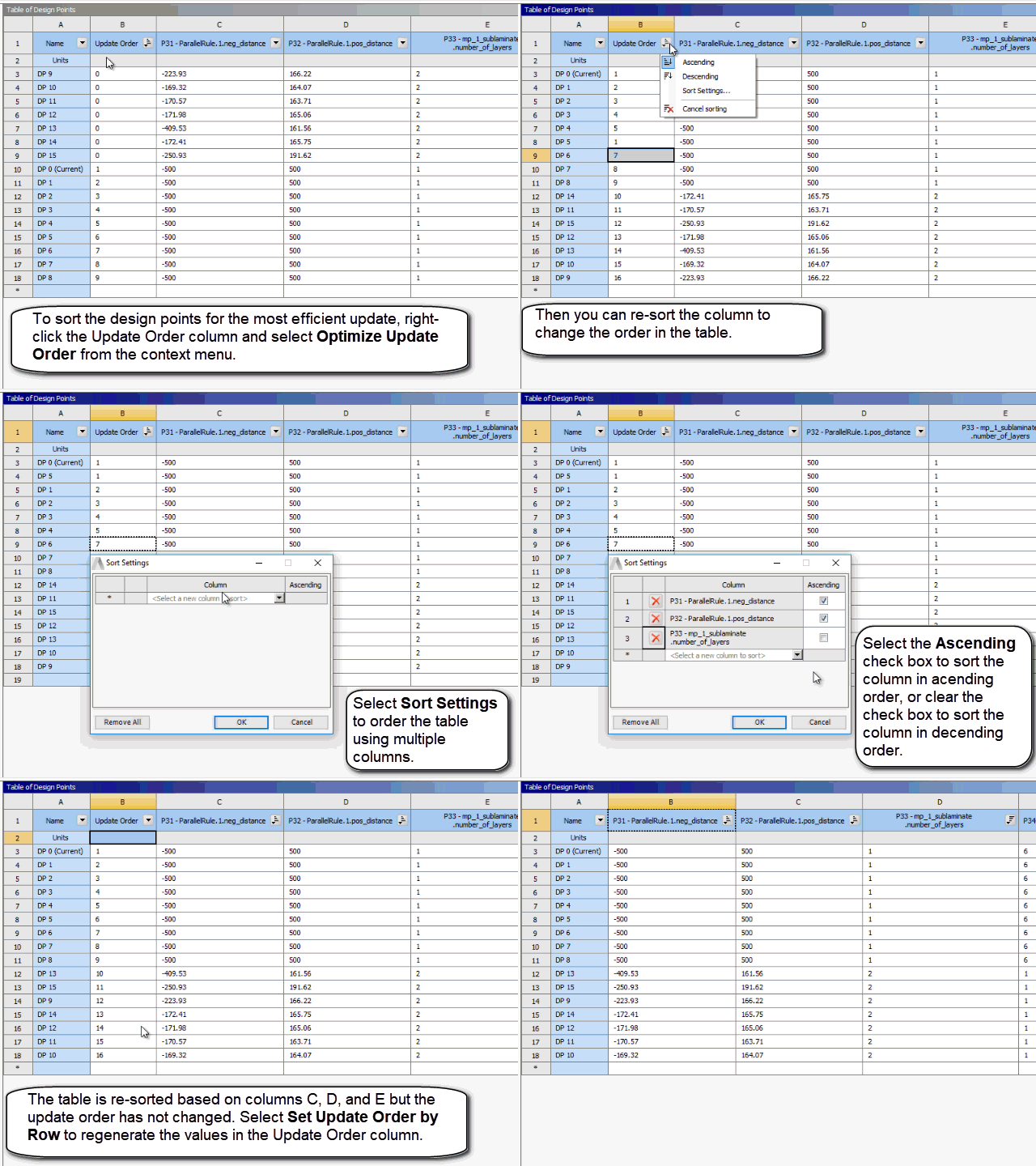
By default, design points are updated in the order in which they appear in the design points table. The Update Order column shows the order number for each design point. To view the column, right-click in the table and select from the context menu.
To change the order that design points are updated in, select from the following options:
Right-click the table and select from the context menu.
An optimal update order is determined by an analysis of parameter dependencies in the project and a scan of parameter values across all design points. The Update Order value for each design point is updated automatically.
Note: The primary goal of Optimize Update Order is to reduce the number of geometry and mesh system updates. In general, the optimized order is driven by the order of the update tasks, which means that the components are updated depending on their order in the system, their data dependencies, their parameter dependencies, and the state of the parameters. This works best in a horizontal schematic with geometry as the first separate system. In a single vertically-integrated system project, the parameters defined in the upper components are considered the most important. In some cases, because of the order of parameter creation or the presence of engineering data parameters, you may find that the first columns are not geometry parameters. In this case, Ansys recommends that you use the Optimize Update Order option to sort by geometry parameters.
Edit the values in the Update Order column.
Sort the table by one or several columns and then right-click in the table and select .
The Update Order value for each design point is regenerated to match the sorting of the table.
The following Show-Me animation is presented as an animated GIF in the online help. If you are reading the PDF version of the help and want to see the animated GIF, access this section in the online help. The interface shown may differ slightly from that in your installed product.

When a design point is updated, the solver is initialized with data. Design points with valid retained data use that as their initialization data. Other design points either:
Initialize with the data of the design point designated as current ()
Initialize starting from the data of the previously updated design point ().
Using the initialization value works best when:
Sequential design points share the same geometry. For example, if DP 2 has the same geometry as DP 1, but both of these differ from DP 0, changing the default behavior saves the computational cost of updating both the geometry and the mesh for DP 2.
You have modified the design point update order in the Update Order column, either by editing the values manually or by generating them with the option.
The design point update order has been optimized, either by the option or by a DesignXplorer optimization.
To set how design points are initialized:
On the Project Schematic, right-click the Parameter Set bar and select from the context menu.
From the Design Point Initialization drop-down list, select the required initialization value.
For systems using CFD-Post results, you can specify that the results cell is always updated with a design point update operation, even when the update does not affect parameter values.
To set systems using CFD-Post to update with design points:
On the Project Schematic, right-click a CFD-Post Results cell and select from the context menu.
In the Properties pane, select the Always Include in Design Points Update check box.


