


Sketches and generates Line Bodies on the model you have imported into Mechanical. You can create multiple Construction Line objects.
For the newly created line body or bodies, you need to specify a Cross Section and assign a material. Review the Body object reference section for descriptions of all of the associated geometry properties.
Also see the Specifying Construction Geometry section.
Object Properties
The Details Pane properties for this object include the following.
| Category | Properties/Options/Descriptions |
|---|---|
|
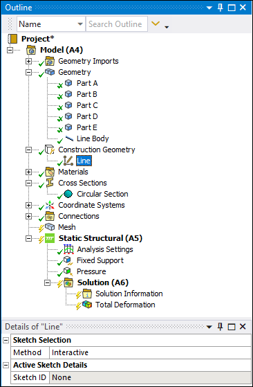
Sketch Selection |
Method: Options for this property include:
|
|
Active Sketch Details |
Sketch ID: Read-only property that shows an application defined ID of the active sketch. You can use this ID for Construction Line ACT APIs. Association Type: Read-only property that shows the entity type for the active sketch. Options include Geometric and Coordinate System. Association ID: Read-only property that shows the ID of the sketch’s object based on the setting of the Association Type property, either Geometric or Coordinate System. If set to Geometric, the ID is a geometric entity ID (See “GeoEntityById” in the ACT API Reference Guide). If set to Coordinate System, the ID is an object ID (the Coordinate System’s object in the Outline). Note: These ID values are compatible with the Mechanical ACT APIs. |
|
Image Plane Properties |
The properties of this category enable you to import and overlay an image on your model to accurately sketch line bodies on or around your model. Image File: Import an image that you will overlay on your model and use to accurately sketch one or more line segments. Coordinate System: Specify where to place your image based on a Coordinate System. Show Coordinate System: Show the selected Coordinate System triad on the model. Options include or (default). Width: Specify the physical width of your image. For the best results, it is recommended that the ratio of physical width to physical height matches the aspect ratio of your image. Height: Specify the physical height of your image. For the best results, it is recommended that the ratio of physical width to physical height matches the aspect ratio of your image. Translucency: Increasing the value makes your image more and more transparent which may help you sketch a more accurate line. Horizontal Flip: Reverse your image horizontally. Vertical Flip: Reverse your image vertically. |
Tree Dependencies
Insertion Methods
Use any of the following methods after highlighting Model object:
Right-click Options
In addition to common right-click options, relevant right-click options for this object include:
> .
>
API Reference
See the Construction Line section of the ACT API Reference Guide for specific scripting information.