


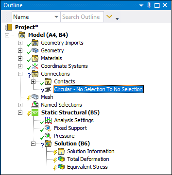
Defines a structural element that carries a load primarily in bending.
 | |
 |
Object Properties
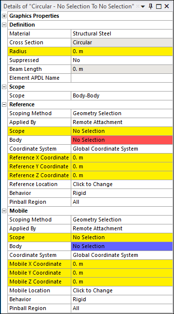
The Details Pane for this object includes the following properties.
| Category | Properties/Options/Descriptions | |||||||||||||||
|---|---|---|---|---|---|---|---|---|---|---|---|---|---|---|---|---|
|
Graphics Properties |
Visible: Toggle the visibility of the beam on and off. | |||||||||||||||
|
Definition |
Material: Material property defined in the Engineering Data Workspace. Cross Section: Read-only indication. Radius Beam Length: Read-only property that displays the actual length of the beam that is calculated using the end points from the scoping of the Reference and Mobile categories. Element APDL Name: Optional property that enables you to manually define an APDL parameter (in the input file) and assign the parameter value as the element of the Beam. This facilitates easy programmatic identification of the element of the Beam for later use/reference in a Commands (APDL) object. | |||||||||||||||
|
Scope - Information on springs also applies to beams. |
Scope: Options include Body-Body or Body-Ground. | |||||||||||||||
|
Reference - Information on springs also applies to beams. |
The following properties are available when the Scope property is set to Body-Body:
The following properties display for either Body-Body or Body-Ground scoping when the Applied By property is set to .
| |||||||||||||||
|
Mobile - Information on springs also applies to beams. |
The following properties are available when the Scope property is set to Body-Body:
The following properties display for either Body-Body or Body-Ground scoping when the Applied By property is set to .
|
Tree Dependencies
Valid Parent Tree Object: Connections.
Valid Child Tree Objects: Commands, Comment, Figure, and Image.
Insertion Methods
Use any of the following methods after highlighting Connections object:
Select Beam > or Beam > , as applicable on Connections Context Tab.
Right-click the Connections object or in the Geometry window > .
Right-click Options
In addition to common right-click options, relevant right-click options for this object include:
Enable/Disable Transparency: Similar behavior to feature in Contact Region.
Promote Remote Point (when the Applied By property is set to ).
API Reference
See the Beam section of the ACT API Reference Guide for specific scripting information.
Additional Related Information
See the following sections for more information: