mesh/auto-meshEnables you to generate the volume mesh automatically. Specify a mesh object name for object-based auto mesh; if no name is given, face zone based auto mesh is performed. Specify the mesh elements to be used when prompted. Specify whether to merge the cells into a single zone or keep the cell zones separate. For face zone based meshing, specify whether automatically identify the domain to be meshed based on the topology information.
Note:You can specify the meshing parameters for the mesh elements (prisms, pyramids or non-conformals, tet, hex or poly) using either the respective dialog boxes or the associated text commands prior to using the
auto-meshcommand.
mesh/auto-mesh-controls/Enters the auto-mesh-controls submenu
mesh/auto-mesh-controls/backup-objectEnables creation of a backup of the surface mesh before volume meshing starts. This option is enabled by default.
mesh/auto-prefix-cell-zonesEnables you to specify a prefix for cell zones created during the auto mesh procedure.
Note: The
auto-prefix-cell-zonescommand is not relevant for object-based meshing, where the cell zone names are generated based on the material points and the objects used to generate the mesh object.mesh/cavity/Enters the cavity menu.
mesh/cavity/add-zonesEnables you to create a cavity for adding new zones to the existing volume mesh.
mesh/cavity/merge-cavityEnables you to merge the specified cavity domain with the parent domain.
During the merging operation, the cavity cell zones merges with the zones in the parent domain. The wall boundaries extracted from the interior zones will be converted to interior type and merged with the corresponding zones in the parent domain.
mesh/cavity/regionEnables you to create a cavity to modify the existing volume mesh in the specified region.
mesh/cavity/remove-zonesEnables you to create a cavity for removing zones from the existing volume mesh.
mesh/cavity/replace-zonesEnables you to create a cavity for removing a set of zones from an existing volume mesh and replacing them with new set of zones.
mesh/cell-zone-conditions/Contains options for copying or clearing cell zone conditions when a case file is read.
mesh/cell-zone-conditions/clearClears the cell zone conditions assigned to the specified zones.
mesh/cell-zone-conditions/clear-allClears the cell conditions assigned to all the zones.
mesh/cell-zone-conditions/copyEnables you to copy the cell zone conditions from the zone selected to the zones specified.
mesh/check-meshChecks the mesh for topological errors.
mesh/check-qualityEnables you to ensure that the mesh quality is appropriate before transferring the mesh to the solution mode.
mesh/check-quality-levelEnables you to report additional quality metrics when set to 1.
In addition to the orthogonal quality and Fluent aspect ratio, additional metrics such as cell squish and skewness will be reported when the
check-quality-levelis set to1.mesh/clear-meshEnables you to generate a new mesh by deleting the internal mesh and leaving only the boundary faces and nodes.
mesh/create-heat-exchangerCreates the heat exchanger mesh. You need to specify the method for selecting the Location coordinates (by Position or Nodes), the location coordinates, the parameters for setting up mesh density (by Interval or Size), and the number of intervals (sizes) between points (nodes) 1–2, 1–3, 1–4. Also specify the object/zone name prefix and enable creating the mesh object, if required.
mesh/cutcell/Enters the cutcell menu.
Note: This menu is no longer supported, and will be removed in a future release.
mesh/cutcell/createCreates the CutCell mesh by performing the initialize, refine, snap, and improve operations sequentially.
mesh/cutcell/create-prismCreates the prism layers on the recovered boundary based on the zone-specific prism parameters set. Specify the cell zones into which the prism layers are to be grown and the gap factor as appropriate.
mesh/cutcell/modify/Enters the cutcell modify menu.
mesh/cutcell/modify/auto-node-moveEnables you to use the Auto Node Move utility to improve the CutCell mesh quality.
mesh/cutcell/modify/cavity-remeshingEnables you to use the Cavity Remeshing utility to improve the CutCell mesh quality near the boundary.
Note: Face zones of type internal are recovered as type wall in the cutcell mesher. These should be reset to type internal before using the cavity remesher.
mesh/cutcell/modify/post-morph-improveImproves the quality of the CutCell mesh post-prism generation.
mesh/cutcell/modify/rezone-multi-connected-facesEnables you to resolve multi-connected configurations on the CutCell boundary. Specify an appropriate value for the critical count for contiguous manifold faces.
An example is shown in Figure 8.1: Rezoning Multiply Connected Faces where the multiply connected faces around the surface are removed.
mesh/cutcell/modify/split-boundaryCreates a copy of the specified CutCell boundary zones and makes the boundary mesh conformal at the hanging-nodes on the copied zones. The new zones will be named based on the original zone names and prefixed by
split-.
mesh/cutcell/objects/Enters the
objectsmenu.mesh/cutcell/objects/change-object-typeEnables you to change the object type (
geomormesh).mesh/cutcell/objects/check-meshChecks the mesh on the specified objects for connectivity and orientation of faces. The domain extents, volume statistics, and face area statistics will be reported along with the results of other checks on the mesh.
mesh/cutcell/objects/createCreates the object based on the priority, cell zone type, face zones, edge zones, and object type specified. You can specify the object name or retain the default blank entry to have the object name generated automatically.
mesh/cutcell/objects/create-and-activate-domainCreates and activates the domain comprising the face zones from the objects specified.
mesh/cutcell/objects/create-groupsCreates a face group and an edge group comprising the face zones and edge zones included in the specified objects, respectively.
mesh/cutcell/objects/create-intersection-loopsEnables you to create intersection loops for objects.
The
collectivelyoption creates an interior edge loop at the intersection between two adjacent face zones included in the same object and between multiple objects.The
individuallyoption creates an interior edge loop at the intersection between two adjacent face zones included in the same object.
mesh/cutcell/objects/create-multipleCreates multiple objects by creating an object per face zone specified. The objects will be named automatically based on the prefix and priority specified.
mesh/cutcell/objects/create-new-mesh-object/Contains options for creating a new mesh object by wrapping or remeshing existing objects.
mesh/cutcell/objects/create-new-mesh-object/remeshCreates a new mesh object by remeshing geometry objects individually or collectively.
mesh/cutcell/objects/create-new-mesh-object/wrapCreates a new mesh object by wrapping the specified objects individually or collectively.
mesh/cutcell/objects/deleteDeletes the specified objects.
mesh/cutcell/objects/delete-allDeletes all the defined objects.
mesh/cutcell/objects/delete-all-geomDeletes all the defined
geomobjects.mesh/cutcell/objects/delete-unreferenced-faces-and-edgesDeletes all the faces and edges that are not included in any defined objects.
mesh/cutcell/objects/extract-edgesExtracts the edge zones from the face zones included in the specified objects, based on the edge-feature-angle value specified (
/mesh/cutcell/objects/set/set-edge-feature-angle).mesh/cutcell/objects/improve-feature-captureEnables you to imprint the edges comprising the object on to the object face zones to improve feature capture for mesh objects. You can specify the number of imprinting iterations and additional aggressive imprinting iterations to be performed.
mesh/cutcell/objects/improve-object-qualityThis command is not relevant for CutCell meshing.
mesh/cutcell/objects/join-intersect/The commands in this sub-menu are not relevant for CutCell meshing.
mesh/cutcell/objects/listLists the defined objects, indicating the respective cell zone type, priority, face zones and edge zones comprising the object, object type, and object reference point in the console.
mesh/cutcell/objects/mergeMerges the specified objects into a single object.
mesh/cutcell/objects/merge-edgesMerges all the edge zones in an object into a single edge zone.
Note: If the object is composed of edge zones of different types (boundary and interior), the edge zones of the same type (boundary or interior) will be merged into a single edge zone.
mesh/cutcell/objects/merge-nodesMerges the free nodes at the object level based on the specified tolerance or using a tolerance that is a specified percentage of shortest connected edge length.
mesh/cutcell/objects/merge-voidsEnables you to merge voids in the mesh object after the sewing operation. This command is not relevant for CutCell meshing.
mesh/cutcell/objects/merge-wallsMerges all the face zones of type
wallin an object into a single face zone.mesh/cutcell/objects/remove-gaps/Contains options for removing gaps between mesh objects. The commands in this sub-menu are not relevant for CutCell meshing.
mesh/cutcell/objects/rotateRotates the objects based on the angle of rotation, pivot point, and axis of rotation specified.
mesh/cutcell/objects/scaleScales the objects based on the scale factors specified.
mesh/cutcell/objects/separate-faces-by-angleSeparates the face zones comprising the object based on the angle specified.
mesh/cutcell/objects/separate-faces-by-seedSeparates the face zones comprising the object based on the seed face specified.
mesh/cutcell/objects/set/Contains the following options:
mesh/cutcell/objects/set/set-edge-feature-angleSets the edge feature angle to be used for extracting edge zones from the face zones included in the objects.
mesh/cutcell/objects/set/show-edge-zones?Displays the edge zones comprising the objects drawn in the graphics window.
mesh/cutcell/objects/set/show-face-zones?Displays the face zones comprising the objects drawn in the graphics window.
mesh/cutcell/objects/translateTranslates the objects based on the translation offsets specified.
mesh/cutcell/objects/updateEnables you to update the objects defined when the face and/or edge zones comprising the object have been deleted.
mesh/cutcell/objects/wrap/Contains options for the object wrapping operation. The commands in this sub-menu are not relevant for CutCell meshing.
mesh/cutcell/set/Enters the CutCell settings menu.
mesh/cutcell/set/auto-delete-dead-zones?Controls the automatic deleting of the dead zones in the CutCell mesh.
mesh/cutcell/set/auto-delete-solid-zones?Controls the automatic deleting of the solid zones in the CutCell mesh.
mesh/cutcell/set/create-material-pointEnables you to define a material point.
mesh/cutcell/set/delete-all-material-pointsEnables you to delete all defined material points.
mesh/cutcell/set/delete-material-pointDeletes the specified material point.
mesh/cutcell/set/list-material-pointsLists all the defined material points.
mesh/cutcell/set/max-initial-cellsSpecifies the maximum number of cells in the initial Cartesian grid.
mesh/cutcell/set/set-cutcell-quality-methodEnables you to set the quality measure for the improve operation. The default measure used is the orthoskew metric.
mesh/cutcell/set/set-post-morph-parametersEnables you to set parameters for improving the CutCell mesh post-prism generation using the command
/mesh/cutcell/modify/post-morph-improve.mesh/cutcell/set/set-post-snap-parametersEnables you to set parameters for improving the CutCell mesh quality.
mesh/cutcell/set/set-thin-cut-face-zonesEnables you to specify the face zones constituting the thin regions to be recovered during the CutCell meshing process.
mesh/cutcell/set/set-thin-cut-edge-zonesEnables you to specify the edge zones defining the features in thin regions to be recovered during the CutCell meshing process.
mesh/cutcell/size-functions/Enters the size functions menu.
mesh/cutcell/size-functions/computeComputes the size field based on the defined parameters.
mesh/cutcell/size-functions/contours/Enters the contours sub-menu.
mesh/cutcell/size-functions/contours/drawDisplays contours in the graphics window. Compute the size field using
/size-functions/computeor read in a size field file prior to displaying the contours of size.mesh/cutcell/size-functions/contours/set/refine-facets?Enables you to specify smaller facets if the original are too large. Default is
no.
mesh/cutcell/size-functions/createDefines the size function based on the specified parameters.
mesh/cutcell/size-functions/create-defaultsCreates default size functions based on face and edge curvature and proximity.
mesh/cutcell/size-functions/deleteDeletes the specified size function or the current size field.
mesh/cutcell/size-functions/delete-allDeletes all the defined size functions.
mesh/cutcell/size-functions/listLists all the defined size functions and the corresponding parameter values defined.
mesh/cutcell/size-functions/list-periodicity-filterLists the details of the source zone and rotational periodic parameters specified for the size field.
mesh/cutcell/size-functions/reset-global-controlsResets the values for the global controls to the defaults.
mesh/cutcell/size-functions/set-global-controlsSets the values for the global minimum and maximum size, and growth rate.
mesh/cutcell/size-functions/set-periodicity-filterEnables you to apply periodicity to the size field by selecting one source face zone.
Note: Ensure that periodicity is previously defined in the Make Periodic Boundaries dialog box.
Only rotational periodicity is supported, translational periodicity is not supported currently.
mesh/cutcell/size-functions/set-prox-gap-toleranceSets the tolerance relative to minimum size to take gaps into account. Gaps whose thickness is less than the global minimum size multiplied by this factor will not be regarded as a proximity gap.
mesh/cutcell/size-functions/set-scaling-filterEnables you specify the scale factor, and minimum and maximum size values to filter the size output from the size field.
mesh/cutcell/size-functions/triangulate-quad-faces?Identifies the zones comprising non-triangular elements and uses a triangulated copy of these zones for computing the size functions.
mesh/cutcell/size-functions/un-set-periodicity-filterRemoves periodicity from the size field.
mesh/cutcell/size-functions/use-cad-imported-curvature?Allows you to use curvature data from the nodes of the CAD facets.
mesh/domains/Enters the domain menu.
mesh/domains/activateActivates the specified domain for meshing or reporting operations.
mesh/domains/createCreates a new domain based on the specified boundary face zones. Ensure valid boundary zones are specified; specifying invalid zones will generate an error.
mesh/domains/create-by-cell-zoneCreates a new domain based on the specified cell zone.
mesh/domains/create-by-pointCreates a new domain based on the specified
Note: The create-by-point option works only for cases with no overlapping face zones.
mesh/domains/deleteDeletes the specified domain.
mesh/domains/drawDisplays the boundary face zones of the specified domain.
mesh/domains/printPrints the information for the specified domain.
mesh/hexcore/Enters the hexcore menu.
mesh/hexcore/controls/Enters the hexcore controls menu.
mesh/hexcore/controls/avoid-1:8-cell-jump-in-hexcoreDetermines the types of cells (large cells, small cells, or both) that are going to be replaced with pyramid and tet cells in order to avoid any 1:8 cell jumps in the hexcore region. The default is
noandsmall-cells.mesh/hexcore/controls/buffer-layersSets the number of addition cells to mark for subdivision.
mesh/hexcore/controls/compute-max-cell-lengthComputes the maximum cell length for the hexcore mesh.
mesh/hexcore/controls/define-hexcore-extents?Enables you to extend the hexcore mesh to specified domain extents and/or selected planar boundaries. When enabled, the
outer-domain-paramssub-menu will be available.mesh/hexcore/controls/delete-dead-zones?Toggles the automatic deleting of the dead zones.
mesh/hexcore/controls/maximum-cell-lengthSets the maximum cell length for the hex cells in the domain.
mesh/hexcore/controls/maximum-initial-cellsSpecifies the maximum number of cells in the initial Cartesian mesh.
mesh/hexcore/controls/non-fluid-typeSelects the default non-fluid cell zone type. After the mesh is initialized, any non-fluid zones will be set to this type. If the mesh includes multiple regions (for example, the problem for which you are creating the mesh includes a fluid zone and one or more solid zones), and you plan to refine all of them using the same refinement parameters, modify the Non-Fluid Type before generating the hexcore mesh.
Note: For zone-based meshing, if any cell zone has at least one boundary zone type as inlet, it will automatically be set to fluid type. For object based meshing, volume region type is used to determine the cell zone type.
mesh/hexcore/controls/octree-hexcore?Speeds up hexahedral core generation by enabling the octree technique for hexcore mesh generation. This option is disabled by default.
Body-of-influence sizing may be used for refinement.
This option does not support hexcore generation up to boundaries.
mesh/hexcore/controls/outer-domain-params/Contains options for defining the outer domain parameters. This sub-menu is available only when
define-hexcore-extents?is enabled.mesh/hexcore/controls/outer-domain-params/specify-coordinates?Enables you to specify the extents of the hexcore outer box using the
coordinatescommand.mesh/hexcore/controls/outer-domain-params/coordinatesSpecifies the extents (min and max coordinates) of the hexcore outer box. This command is available when the
specify-coordinates?option is enabled.mesh/hexcore/controls/outer-domain-params/specify-boundaries?Enables you to specify selected boundaries to which the hexcore mesh is to be generated using the
boundariescommand.mesh/hexcore/controls/outer-domain-params/boundariesSpecifies the boundaries to which the hexcore mesh is to be generated when the
specify-boundaries?option is enabled. After specifying the boundaries, theauto-align?,delete-old-face-zones?, andlistoptions will also be available.mesh/hexcore/controls/outer-domain-params/auto-align?Enables you to axis-align non-aligned planar boundaries to which hexcore mesh is to be generated. This option is available only when the
specify-boundaries?option is enabled and the boundaries are specified.mesh/hexcore/controls/outer-domain-params/auto-align-toleranceSpecifies the tolerance for aligning boundary zones when
auto-align?is enabled.mesh/hexcore/controls/outer-domain-params/auto-align-boundariesAligns the boundary zones specified (using the
boundariescommand) with the tolerance specified \ (using theauto-align-tolerancecommand) whenauto-align?is enabled.mesh/hexcore/controls/outer-domain-params/delete-old-face-zones?Enables you to delete the original tri face zones that have been replaced during the hexcore meshing process. This option is available only when the
specify-boundaries?option is enabled and the boundaries are specified.mesh/hexcore/controls/outer-domain-params/listLists the boundaries to which the hexcore mesh is to be generated. This option is available only when the
specify-boundaries?option is enabled and the boundaries are specified.
mesh/hexcore/controls/peel-layersSpecifies the distance for the hexcore interface to peel-back from the boundary. The default value is 0. The higher the value of peel layer, the bigger the distance between the hexcore interface and the boundary.
mesh/hexcore/controls/print-region-based-sizingDisplays local sizing settings (max cell length and growth rate) for specified region(s).
mesh/hexcore/controls/set-region-based-sizingAllows you to specify local sizing settings (max cell length and growth rate) for specified region(s).
mesh/hexcore/controls/skip-tet-refinement?Enables you to omit the tetrahedral refinement phase for reducing total cell count (default is no). Hex cell count is unaffected.
Tip: You should use
peel-layersequal 0 when this option is enabled.Warning: This option may leave narrow regions without hexcore mesh. Tetrahedral cells with lower quality may be created in such regions, reducing the overall mesh quality.
mesh/hexcore/createEnables you to create the hexcore mesh according to the specified parameters.
mesh/hexcore/local-regions/Enters the hexcore local refinement region sub-menu.
mesh/hexcore/local-regions/activateEnables you to activate the specified local regions for refinement.
mesh/hexcore/local-regions/deactivateEnables you to deactivate the specified local regions for refinement.
mesh/hexcore/local-regions/defineDefines the local region according to the specified parameters.
mesh/hexcore/local-regions/deleteDeletes the specified refinement region.
mesh/hexcore/local-regions/ideal-hex-volReports the ideal hex volume for the given edge length.
mesh/hexcore/local-regions/initCreates a default region encompassing the entire geometry.
mesh/hexcore/local-regions/list-all-regionsLists the defined and active regions in the console.
mesh/hexcore/merge-tets-to-pyramids?Enables the
merge-tets-to-pyramidscommand to reduce the total cell count.If
skip-tet-refinementis enabled, pairs of tets will be merged into pyramids. Hexcore count is unaffected.
mesh/laplace-smooth-nodesApplies a Laplacian smoothing operator to the mesh nodes. This command can be used for smoothing of all cell types, including prismatic cells.
mesh/list-mesh-parameterShows all mesh parameters.
mesh/manage/Enters the manage cell zones menu.
mesh/manage/active-listLists all active zones.
mesh/manage/adjacent-face-zonesLists all face zones that refer to the specified cell zone.
mesh/manage/auto-set-activeSets the active zones based on points that are defined in an external file. For each zone you want to activate, you need to specify the coordinates of a point in the zone, the zone type (for example, fluid), and (optionally) a new name. A sample file is shown below:
((1550.50 -466.58 896.41) fluid heater-#)
((1535.83 -643.14 874.71) fluid below-heater-#)
((1538.73 -444.28 952.69) fluid above-heater-#)
((1389.18 -775.51 825.97) fluid plenum-#)
Here, four fluid zones are identified, renamed, and activated. Any zone that you identify in the file will automatically be activated. The
#indicates that the mesher should append the appropriate ID number for the zone.Warning: This command is valid only for tet meshes.
mesh/manage/change-prefixEnables you to change the prefix for the cell zone.
mesh/manage/copyCopies all nodes and faces of specified cell zones.
mesh/manage/deleteDeletes a cell zone, along with its associated nodes and faces. When deleting cell zones that contain poly cells, you will be warned that the original mesh must be deleted and the original faces restored prior to remeshing the volumetric region.
mesh/manage/get-material-pointPrints the coordinates of the material point for the specified cell zone.
Note: If the cell zone is non-contiguous, the
get-material-pointcommand will print a list of material points, one for each contiguous region.mesh/manage/idSpecifies a new cell zone ID. If a conflict is detected, the change will be ignored.
mesh/manage/listPrints information on all cell zones.
mesh/manage/mergeMerges two or more cell zones.
Note: For object-based merge, the selected zones must be in the same volumetric region. If not, you will have to merge the volumetric regions first using
/objects/volumetric-regions/merge. If the volumetric regions cannot be merged because they are not contiguous, you will have to delete the object(s) only before merging the cell zones.mesh/manage/merge-dead-zonesEnables you to merge dead zones having a cell count lower than the specified threshold value, with the adjacent cell zone. The result of the merge operation is determined by the type of the adjacent cell zone and the shared face area. The priority for merging with the adjacent cell zone based on type is fluid > solid > dead (that is, merging with an adjacent fluid zone takes priority over merging with an adjacent solid zone, which in turn takes priority over merging with a dead zone). Also, if the adjacent zones are of the same type (for example, fluid), the zone will be merged with the zone having the largest shared face area.
mesh/manage/nameEnables you to rename a cell zone.
mesh/manage/originSpecifies a new origin for the mesh, to be used for cell zone rotation. The default origin is (0,0,0).
mesh/manage/revolve-face-zoneGenerates cells by revolving a face thread.
mesh/manage/rotateRotates all nodes of specified cell zones by a specified angle.
mesh/manage/rotate-modelRotates all nodes of the model by a specified angle.
mesh/manage/scaleScales all nodes of specified cell zones by a specified factor.
mesh/manage/scale-modelScales all nodes of the model by a specified factor.
mesh/manage/set-activeSets the specified cell zones to be active.
mesh/manage/translateTranslates all nodes of specified cell zones by a specified vector.
mesh/manage/translate-modelTranslates all nodes of the model by a specified vector.
mesh/manage/typeChanges the type and name of a cell zone.
mesh/modify/Enters the mesh modify menu.
mesh/modify/auto-improve-warpEnables you to improve face warp by node movement. Specify the appropriate cell zones and boundary zones, the maximum warp, the number of iterations per face to be improved, and the number of iterations of the automatic node movement procedure (default, 4).
mesh/modify/auto-node-moveEnables you to improve the mesh quality by node movement. Specify the appropriate cell zones and boundary zones, the quality limit based on the quality measure selected, dihedral angle, the number of iterations per node to be moved and the number of iterations of the automatic node movement procedure (default, 1). You can also choose to restrict the movement of boundary nodes along the surface.
mesh/modify/clear-selectionsClears all items from the selection list.
mesh/modify/deselect-lastDeselects the last item you selected using the
select-entitycommand.mesh/modify/extract-unused-nodesPlaces all unused nodes in a separate interior node zone.
mesh/modify/list-selectionsLists all items in the selection list.
mesh/modify/list-skewed-cellsLists cells with skewness in a specified range.
mesh/modify/mesh-nodeAttempts to introduce a new node into the existing mesh.
mesh/modify/mesh-nodes-on-zoneInserts nodes associated with node or face zone into the volume mesh.
Important: If a face zone is specified, the faces are deleted before the nodes are introduced into the mesh.
mesh/modify/neighborhood-skewReports the maximum skewness of cells using the specified node.
mesh/modify/refine-cellAttempts to refine the cells in the probe list by introducing a node nears its centroid. This technique is useful for removing very flat cells near the boundary when boundary sliver removal is not possible. After refining the cell, you should smooth the mesh.
mesh/modify/repair-negative-volume-cellsRepairs negative volume cells by moving nodes. Specify the appropriate boundary zones, the number of iterations per node to be moved, dihedral angle, whether to restrict the movement of boundary nodes along the surface, and the number of iterations of the automatic node movement procedure (default, 1).
mesh/modify/select-entityAdds an entity (face, node, cell, etc.) to the selection list.
mesh/modify/smooth-nodeApplies Laplace smoothing to the nodes in the selection list.
mesh/non-conformals/Enters the non-conformals menu.
mesh/non-conformals/controls/Enters the non-conformals controls menu.
mesh/non-conformals/controls/enable?Toggles the creation of a non-conformal interface.
mesh/non-conformals/controls/retri-method/Specifies the method to be used for retriangulating the quad faces on the non-conformal zones.
mesh/non-conformals/controls/retri-method/prismRemeshes the prism-side quad zones named prism-side* or *-quad*.
mesh/non-conformals/controls/retri-method/quad-splitSplits the quad faces diagonally into tri faces.
mesh/non-conformals/controls/retri-method/remeshRemeshes all the quad faces based on the edge and surface feature angle specified.
mesh/non-conformals/createCreates the non-conformal interface on the specified face zones using the specified retriangulation method.
mesh/non-conformals/separateEnables you to separate the face zones comprising the non-conformal interface between the cell zones specified. Specify the cell zones where the interface is non-conformal, an appropriate gap distance, and the critical angle to be used for separating the face zones. You can also choose to orient the boundary face zones after separation and additionally write a journal file for the separation operation.
Note: If you choose to write a journal file when using the
/mesh/non-conformals/separatecommand to separate the mesh interface zones, you can read the journal file to create the mesh interface automatically in solution mode.
mesh/poly/Enters the polyhedral mesh generation menu.
mesh/poly/collapseMerge nodes to remove short edges and small faces. The decision threshold uses edge size ratio, face size ratio, and (face) area fraction.
mesh/poly/controls/Enters the controls menu for setting poly parameters.
mesh/poly/controls/cell-sizingSets cell volume distribution function as
geometric,linear, orsize-field.mesh/poly/controls/edge-size-ratioSets the threshold for the size ratio of two connected edges. Recommended range is 20 to 200.
mesh/poly/controls/face-size-ratioSets the threshold for the size ratio of two faces on one cell. Recommended range is 100 to 300.
mesh/poly/controls/feature-angleSets the minimum threshold that should be preserved as a feature.
mesh/poly/controls/improve?Enables poly mesh improvement by smoothing based on the
smooth-controls.mesh/poly/controls/merge-skewSets the minimum skewness threshold for cell merge.
mesh/poly/controls/non-fluid-typeSelects the default type for non-fluid zones.
mesh/poly/controls/remesh-skewSets the target skewness when remeshing.
mesh/poly/controls/sliver-cell-area-fractionSets the threshold for the area of a single face to the cell surface area. Recommended range is 0.00001 to 0.001.
mesh/poly/controls/smooth-controls/Enters the menu for setting smoothing parameters for poly mesh.
mesh/poly/controls/smooth-controls/centroid-smooth-iterationsSets the number of passes for tet-cell centroid smoothing during the poly mesh generation phase.
mesh/poly/controls/smooth-controls/edge-smooth-iterationsSets the number of passes for tet-cell edge smoothing during the poly mesh generation phase.
mesh/poly/controls/smooth-controls/laplace-smooth-iterationsSets the number of passes for tet-cell Laplace smoothing during the poly mesh generation phase.
mesh/poly/controls/smooth-controls/smooth-attemptsSets the maximum number of movements for a single node during poly mesh smoothing.
mesh/poly/controls/smooth-controls/smooth-boundaryEnables boundary smoothing as part of poly cell smoothing. Default is no.
mesh/poly/controls/smooth-controls/smooth-iterationsSets the number of improvement passes over the full poly mesh.
mesh/poly/controls/smooth-controls/smooth-on-layerConstrains movement of nodes to maintain layering during poly mesh smoothing.
mesh/poly/controls/smooth-controls/smooth-skewSets the minimum skewness threshold for poly mesh smoothing.
mesh/poly/improveAllows you to improve the polyhedral mesh quality based on the
quality-method.mesh/poly/local-regions/Enters the local refinement menu.
Note: Poly meshing follows tet meshing. These commands behave like the equivalent commands under
/mesh/tet/local-regions/.mesh/poly/local-regions/activateActivates the specified regions for refinement.
mesh/poly/local-regions/deactivateDeactivates the specified regions for refinement.
mesh/poly/local-regions/defineDefines the refinement region according to the specified parameters.
mesh/poly/local-regions/deleteDeletes the specified refinement region.
mesh/poly/local-regions/ideal-volReports the volume of an ideal tetrahedron for the edge length specified.
mesh/poly/local-regions/initDefines the default refinement region encompassing the entire geometry.
mesh/poly/local-regions/list-all-regionsLists all refinement region parameters and the activated regions in the console.
mesh/poly/local-regions/refineRefines the active cells inside the selected region based on the specified refinement parameters.
mesh/poly/quality-methodAsks you to choose from
internal-default,orthoskeworsquishquality measure for mesh improvement.mesh/poly/remeshImproves the quality in a local region based on the minimum skewness threshold.
mesh/poly-hexcore/Enters the menu for poly-hexcore mesh.
mesh/poly-hexcore/controls/Enters the menu for setting parameters for poly-hexcore mesh.
mesh/poly-hexcore/controls/avoid-1:8-cell-jump-in-hexcoreDetermines the types of cells (large cells, small cells, or both) that are going to be replaced with polyhedra cells in order to avoid any 1:8 cell jumps in the hexcore region. The default is
noandlarge-cells.mesh/poly-hexcore/controls/mark-core-region-cell-type-as-hex?Determines whether or not to apply hexahedra cells in the core region of the mesh. The default value is
yes.mesh/poly-hexcore/controls/only-polyhedra-for-selected-regionsDetermines if polyhedra cells are to be applied to the selected regions.
mesh/prepare-for-solvePrepares the mesh for solving in solution mode by performing a cleanup operation after the volume mesh has been generated. Operations such as deleting dead zones, deleting geometry objects, deleting edge zones, deleting unused faces and nodes are performed during this operation.
mesh/prism/Enters the prism menu.
mesh/prism/controls/Enters the prism controls menu.
mesh/prism/controls/adjacent-zone/Enters the prism adjacent zone controls menu.
mesh/prism/controls/adjacent-zone/project-adjacent-angleDetermines whether or not to project to an adjacent zone. If a zone shares outer nodes with any of the zones from which the layers are being grown (the “base zones”), its angle with respect to the growth direction is compared with this value. If the angle is less than or equal to this value, then the zone will be projected to. The default value is 75 degrees. See Using Adjacent Zones as the Sides of Prisms for details.
mesh/prism/controls/adjacent-zone/side-feature-angleSpecifies the angle used for computing the feature normals.
mesh/prism/controls/check-quality?Enables/disables the checking of volume, skewness, and handedness of each new cell and face.
mesh/prism/controls/improve/Enters the prism smoothing controls menu.
mesh/prism/controls/improve/check-allowable-skew?Enables you to check the skewness of the prism cap for every layer.
mesh/prism/controls/improve/corner-height-weight?When enabled, the offset height at corners with large angles (for example, 270º) is reduced to give a smoother prism cap.
mesh/prism/controls/improve/edge-swap-base-angleSpecifies the maximum allowable angle between the normals of the base faces for skewness-driven edge swapping.
mesh/prism/controls/improve/edge-swap-cap-angleSpecifies the maximum allowable angle between the normals of the cap faces for skewness-driven edge swapping.
mesh/prism/controls/improve/improve-warp?Enables or disables improving of face warp during prism generation. This option is disabled by default.
mesh/prism/controls/improve/left-hand-checkControls checking for left-handedness of faces. The default setting of
0implies face handedness will not be checked. A value of1implies only cap faces will be checked, while2implies faces of all cells in current layer will be checked.mesh/prism/controls/improve/max-allowable-cap-skewSpecifies the maximum skewness allowed for a prism cap face. If the skewness of a cap face exceeds this value, the meshing process will stop and a warning indicates that the skewness for that layer is too high.
mesh/prism/controls/improve/max-allowable-cell-skewSpecifies the cell quality criteria for smoothing and quality checking.
mesh/prism/controls/improve/smooth-improve-prism-cells?Enables you to set the parameters for improving the prism cells after the required prism layers are created. You can select optimized smoothing (
smooth), node movement (improve), or a combination of both to improve the quality. Specify the quality measure to be used, the cell quality threshold, the number of improvement iterations, and the minimum improvement required.
mesh/prism/controls/merge-ignored-threads?Enables you to automatically merge all ignored zones related to a base thread into a single thread. This option is enabled by default. When this option is disabled, more than one ignored thread will be generated per base thread. However, various zones can be created by ignoring this option. They are:
mesh/prism/controls/merge-ignored-threads?*:dwallIs formed due to dangling wall.
mesh/prism/controls/merge-ignored-threads?*:proxIs formed due to proximity.
mesh/prism/controls/merge-ignored-threads?*:ud_normalIs formed due to invalid normal.
mesh/prism/controls/merge-ignored-threads?*:smoothIs formed due to smoothing of ignored regions.
The default value of the tgvar
prism/ignore-extension(for which there is no TUI command) is 1. It means that after the prism generation is over, all the ignored regions are expanded by this number. If we expand say by n times, that is ifprism/ignore-extensionis set to n usingtgsetvar!(with the exclamation mark), more ignored threads will be created because of expanding ignored regions. These regions will be named as follows:*:cell_delete_1, *:cell_delete_2, *:cell_delete_3,....up to \*:cell_delete_nIf
merge-ignored-threads?is enabled, then all these are merged and you finally get only one zone per base thread, named as*:ignore.mesh/prism/controls/morph/Enters the prism morphing controls menu.
mesh/prism/controls/morph/improve-thresholdSpecifies the quality threshold used for improving the quality during the morphing operation.
mesh/prism/controls/morph/morphing-convergence-limitSpecifies the convergence limit for the morphing operation. The morpher uses an iterative solver. It is assumed to have converged when the relative residual is less than this number.
mesh/prism/controls/morph/morphing-frequencySpecifies the frequency of the morphing operation. The number specified denotes the number of prism layers after which the morpher is applied to the remainder of the mesh (for example, a value of 5 indicates that the morpher is applied to the mesh after every 5 prism layers grown).
mesh/prism/controls/normal/Enters the prism normal controls menu.
mesh/prism/controls/normal/bisect-angleIs required for growing prisms out of sharp interior corners. When the value of this angle is set, the normals are automatically projected onto the plane bisecting the angle between faces having an interior angle less than this angle.
mesh/prism/controls/normal/compute-normalComputes the normal for the specified face zone.
mesh/prism/controls/normal/direction-methodSpecifies whether the prism layers should be grown normal to surfaces or along a specified direction vector.
mesh/prism/controls/normal/direction-vectorSpecifies the direction vector for prism extrusion when the
uniformmethod is selected fordirection-method.mesh/prism/controls/normal/ignore-invalid-normals?Enables you to ignore nodes that have poor normals.
mesh/prism/controls/normal/max-angle-changeSpecifies the maximum angle by which the normal direction at a node can change during smoothing.
mesh/prism/controls/normal/orient-mesh-object-face-normalsEnables you to orient the face normals for mesh object boundary zones. Specify the mesh object, region or material point as appropriate, and specify whether walls, baffles or both comprising the prism base zones are to be separated and oriented.
mesh/prism/controls/normal/orthogonal-layersSpecifies the number of layers to preserve orthogonality. All smoothing is deferred until after these layers.
mesh/prism/controls/offset/Enters the prism offset controls menu.
mesh/prism/controls/offset/first-aspect-ratio-minSpecifies the minimum first aspect ratio (ratio of prism base length to prism layer height) for the prism cells.
mesh/prism/controls/offset/min-aspect-ratioSpecifies the minimum aspect ratio (ratio of prism base length to prism layer height) for the prism cells.
mesh/prism/controls/post-ignore/Contains options for setting the parameters for removing poor quality prism cells after the required prism layers are created.
mesh/prism/controls/post-ignore/post-remove-cells?Enables you to set the parameters for removing poor quality prism cells after the required prism layers are created. You can remove cells based on quality, intersection, interior warp, and feature edges. Specify options for removing additional cells in regions of high aspect ratio and feature angle, the number of cell rings to be removed around the marked cells, and options for smoothing the prism boundary and prism side height.
mesh/prism/controls/proximity/Enters the prism proximity controls menu.
mesh/prism/controls/proximity/allow-ignore?Enables you to ignore nodes where the specified maximum shrink factor cannot be maintained.
mesh/prism/controls/proximity/allow-shrinkage?Enables shrinkage while growing prism layers.
mesh/prism/controls/proximity/gap-factorControls the gap between the intersecting prisms layers in the proximity region with respect to the cell size of the prisms.
mesh/prism/controls/proximity/keep-first-layer-offsets?Enables you to retain first layer offsets while performing proximity detection.
mesh/prism/controls/proximity/max-aspect-ratioSpecifies the maximum allowable cell aspect ratio to determine the limit for the shrinkage of prism layers. This option is available only when the
allow-ignore?option is disabled.mesh/prism/controls/proximity/max-shrink-factorSpecifies the shrink factor determining the maximum shrinkage of the prism layers. This option is available only when the
allow-ignore?option is enabled.
mesh/prism/controls/remove-invalid-layer?Removes the last prism layer if it fails in the quality check.
mesh/prism/controls/set-post-mesh-controlsSets controls specific to growing prisms post volume mesh generation.
mesh/prism/controls/split?Enables you to set parameters for splitting the prism layers after the initial prism layers are generated, to generate the total number of layers required. Specify the number of divisions per layer.
mesh/prism/controls/zone-specific-growth/Enters the prism growth controls menu.
mesh/prism/controls/zone-specific-growth/apply-growthApplies the zone-specific growth parameters specified.
mesh/prism/controls/zone-specific-growth/clear-growthClears the zone-specific growth specified.
mesh/prism/controls/zone-specific-growth/list-growthLists the zone-specific growth parameters specified for individual zones in the console.
mesh/prism/createCreates prism layers on one or more boundary face zones based on the offset method, growth method, number of layers, and rate specified.
mesh/prism/improve/Enters the prism improve menu.
mesh/prism/improve/improve-prism-cellsCollects and smooths cells in layers around poor quality cells. Cells with quality worse than the specified threshold value will be identified, and the nodes of the cells surrounding the poor quality cells will be moved to improve quality.
mesh/prism/improve/smooth-brute-force?Forcibly smooths cells if cell skewness is still high after regular smoothing.
mesh/prism/improve/smooth-cell-ringsSpecifies the number of cell rings around the skewed cell used by
improve-prism-cells.mesh/prism/improve/smooth-improve-prism-cellsUses a combination of node movement and optimized smoothing to improve the quality. This command is a combination of the
smooth-prism-cellsandimprove-prism-cellscommands. The cell aspect ratio will also be maintained based on the value specified formax-aspect-ratio.mesh/prism/improve/smooth-prism-cellsEnables optimization based smoothing of prism cells. The nodes of cells with quality worse than the specified threshold value will be moved to improve quality. The cell aspect ratio will also be maintained based on the value specified for
max-aspect-ratio.mesh/prism/improve/smooth-sliver-skewSpecifies the skewness above which prism cells will be smoothed.
mesh/prism/list-parametersShows all prism mesh parameters.
mesh/prism/mark-ignore-facesEnables you to mark the faces to be ignored during prism meshing.
mesh/prism/mark-nonmanifold-nodesEnables you to mark the non-manifold prism base nodes. A list of the non-manifold nodes will be printed in the console. The faces connected to the non-manifold nodes will also be marked. You can use this command after specifying zone-specific prism settings, prior to generating the prisms to verify that non-manifold configurations do not exist.
mesh/prism/post-ignore/Contains the following options for ignoring prism cells:
mesh/prism/post-ignore/create-cavityCreates a cavity in regions where prism quality is adequate, but the quality of adjacent tetrahedra is poor. The cavity is created based on the tetrahedral cell zone, the quality measure and the corresponding threshold value, and the additional number of cell rings specified. You can create a cavity comprising only tetrahedral cells or optionally include prism cells in the cavity created. When prism cells are also included in the cavity, you can specify whether the non-conformal interface is to be created.
mesh/prism/post-ignore/mark-cavity-prism-capMarks the prism cap faces and tetrahedral cell faces bounding the cavity to be created in regions where prism quality is adequate, but the quality of adjacent tetrahedra is poor. Specify the tetrahedral cell zone, the quality measure and the corresponding threshold value to be used, and the additional number of cell rings based on which the cavity will be created.
mesh/prism/post-ignore/mark-prism-capMarks the prism cap faces for ignoring prism cells in regions of poor quality cells and sharp corners. Specify the prism cell zone and the basis for ignoring prism cells and the relevant parameters. The prism cells can be ignored based on quality, intersection, (both enabled by default), warp, and features (both disabled by default). Specify the quality measure and threshold value to be used for ignoring cells based on quality and (if applicable) the feature edges for ignoring cells based on features. Additionally, specify whether cells are to be marked in regions of high aspect ratio and based on feature angle, and the additional number of cell rings based on which prism cells will be removed.
mesh/prism/post-ignore/post-remove-cellsEnables you to remove prism cells in layers around poor quality cells and sharp corners. Specify the prism cell zone, the basis for ignoring prism cells (quality, intersection, warp, features) and the relevant parameters. Specify the number of cell rings to be removed around the marked cells. Cells will be marked for removal in regions of sharp corners based on quality, intersection, warp, and features (as applicable) and then extended based on the number of cell rings specified. Additional cells will be marked for removal in regions of high aspect ratio and based on feature angle (if applicable) around the exposed prism side. The boundary will be smoothed at feature corners after the prism cells have been removed. The prism-side faces exposed by the removal of the prism cells will be collected in a zone named
prism-side-#, while for a zonewall-n, the faces corresponding to the ignored prism cells will be collected in a zone namedwall-n:ignore. You can also optionally smooth the prism side nodes from the base node to the cap node to create better triangles for the non-conformal interface.
mesh/prism/quality-methodSpecifies the quality method used during prism generation.
mesh/prism/reset-parametersResets all prism parameters.
mesh/prism/split/Contains options for splitting the prism layers after the initial prism layers are generated, to generate the total number of layers required.
mesh/prism/split/splitEnables you to split the prism layers after the initial prism layers are generated, to generate the total number of layers required. Specify the prism cell zones to be split and the number of divisions per layer. You can also choose to use the existing growth rate (default) or specify the growth rate to be used while splitting the prism layers.
mesh/pyramid/Enters the pyramid menu.
mesh/pyramid/controls/Enters the pyramid controls menu.
mesh/pyramid/controls/neighbor-angleSets the threshold dihedral angle used to limit the neighboring faces considered for pyramid creation. For example, if the value is set to 110° and the angle between a given quadrilateral face and a neighboring triangular face is greater than 110°, the resulting pyramid will not include the triangular face.
mesh/pyramid/controls/offset-factorSpecifies the fraction of the computed pyramid height (offset) by which the pyramid heights will be randomly adjusted. The default value is 0, indicating that all pyramids will have the exact height computed. A value of 0.1, for example, will limit each adjustment to ±10% of the computed height.
mesh/pyramid/controls/offset-scalingSpecifies the scaling, to be used to determine the height of the pyramid.
mesh/pyramid/controls/vertex-methodSpecifies the method by which the location of the new vertex of the pyramid will be determined. The
skewnessmethod is used by default.
mesh/pyramid/createCreates a layer of pyramids on the quad face zone.
mesh/rapid-octree/Enters the rapid octree menu, which provides text commands for using the Rapid Octree mesher.
mesh/rapid-octree/boundary-layer-mesh-configuration/Enters the boundary layer mesh configuration menu, which provides text commands for managing the dividing of the isotropic layer at a boundary zone into multiple anisotropic prismatic layers during the mesh creation. This text command menu is only available when
0(Projection) is selected through the/mesh/rapid-octree/boundary-treatmenttext command.mesh/rapid-octree/boundary-layer-mesh-configuration/addAdds a definition for the creation of multiple anisotropic prismatic layers at one or more boundary zones during the mesh creation.
mesh/rapid-octree/boundary-layer-mesh-configuration/deleteDeletes a single definition for the creation of multiple anisotropic prismatic layers during the mesh creation.
mesh/rapid-octree/boundary-layer-mesh-configuration/delete-allDeletes all of the definitions for the creation of multiple anisotropic prismatic layers during the mesh creation.
mesh/rapid-octree/boundary-layer-mesh-configuration/editEdits a definition for the creation of multiple anisotropic prismatic layers during the mesh creation.
mesh/rapid-octree/boundary-layer-mesh-configuration/listLists the settings for all of the definitions for the creation of multiple anisotropic prismatic layers during the mesh creation.
mesh/rapid-octree/boundary-mesh-optimization?Enables boundary mesh optimization, in order to specify that the cells in the layer adjacent to boundary zones are optimized in terms of orthogonal quality at the time of meshing. This text command menu is only available when
0(Projection) is selected through the/mesh/rapid-octree/boundary-treatmenttext command.mesh/rapid-octree/boundary-treatmentSelects the boundary treatment option. Enter
0for the Boundary Projection treatment or1for the Cartesian Snapping treatment.mesh/rapid-octree/bounding-boxDefines/modifies the bounding box around the geometry.
mesh/rapid-octree/createCreates a mesh using the Rapid Octree mesher.
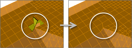
mesh/rapid-octree/delete-poor-quality-cellsDeletes all cells that have an Inverse Orthogonal Quality that is worse than 0.99. When a cell is deleted, new face zones of type symmetry are created for the adjacent cells on the faces that were shared with the deleted cell. This text command should be used with care in order to avoid unwanted effects during the solution (such as solution errors due to bad geometry representation, or even solver divergence). It is only recommended when over 500 bad cells have been produced due to an attempt to improve the geometry resolution or the creation of a boundary layer mesh (see Improve Geometry Resolution or Boundary Layer Mesh in the Fluent User's Guide, respectively).
mesh/rapid-octree/distribute-geometry?Enables/disables the distribution of the input geometry across partitions / compute nodes, so that it is not copied to each process. This reduces the memory requirements of the mesh generation significantly, especially for geometries with a high number of triangles. Note that this geometric distribution is enabled by default and is automatically deactivated if the geometry is not fully enclosed by the defined bounding box.
mesh/rapid-octree/flow-volumeSpecifies the volume to be filled by the mesh.
mesh/rapid-octree/geometryAllows you to apply the Rapid Octree mesher to a defined mesh object or geometry object rather than all available surface zones. Note that using a mesh object with multiple volumetric regions allows you to generate multiple disconnected cell zones that can be coupled by a non-conformal mesh interface in the solution mode; all other input objects result in the creation of a single volume / cell zone.
mesh/rapid-octree/improve-geometry-resolution?Enables an option that improves the geometry resolution, by applying an iterative projection of boundary faces onto the geometry, with the goal of minimizing the distance of the boundary face centroid to the geometry. This “face projection” is then internally iterated with mesh smoothing steps to improve the cell quality. This option is only used when
0(Projection) is selected through the/mesh/rapid-octree/boundary-treatmenttext command.mesh/rapid-octree/mesh-sizing/Enters the mesh sizing menu, which allows you to manage size functions, that is, target mesh sizes for lists of surface zones, as well as local feature angle refinement settings.
mesh/rapid-octree/mesh-sizing/add-surface-sizingAdds a size function definition, that is, a target mesh size for a list of surface zones, along with local feature angle refinement settings. This text command is only available when
0(Projection) is selected through the/mesh/rapid-octree/boundary-treatmenttext command.mesh/rapid-octree/mesh-sizing/boundary-cell-sizeSets the default cell size for the geometry.
mesh/rapid-octree/mesh-sizing/change-surface-sizingChanges a size function definition. This text command is only available when
0(Projection) is selected through the/mesh/rapid-octree/boundary-treatmenttext command.mesh/rapid-octree/mesh-sizing/clear-all-surface-sizingsDeletes all size function definitions. This text command is only available when
0(Projection) is selected through the/mesh/rapid-octree/boundary-treatmenttext command.mesh/rapid-octree/mesh-sizing/delete-surface-sizingDeletes a single size function definition. This text command is only available when
0(Projection) is selected through the/mesh/rapid-octree/boundary-treatmenttext command.mesh/rapid-octree/mesh-sizing/feature-angle-refinementDefines a global angular threshold and number of refinement levels for features. This text command is only available when
0(Projection) is selected through the/mesh/rapid-octree/boundary-treatmenttext command.mesh/rapid-octree/mesh-sizing/list-surface-sizingsLists all of the size function definitions. This text command is only available when
0(Projection) is selected through the/mesh/rapid-octree/boundary-treatmenttext command.mesh/rapid-octree/mesh-sizing/max-cell-sizeSets the maximum cell size in the octree mesh.
mesh/rapid-octree/mesh-sizing/surface-transition-layersSets the minimum number of layers of constant-size cells that are added to the layer adjacent to the surfaces of the geometry. These cells are generally isotropic, with the dimensions determined by the surface mesh.
mesh/rapid-octree/mesh-sizing/volume-transition-exponentControls the transition from fine cells near the surfaces to the coarse cells deeper in the fluid volume. Enter 0 for the fastest possible transition, or higher numbers for a slower transition; as the value increases, so too will the thickness of cell layers of the same size at each stage of the transition. The number of layers at each intermediate stage of coarsening will be at least 2 to the power of the number you enter here.
mesh/rapid-octree/refinement-regions/Enters the rapid octree refinement regions menu, which allows you to manage the refinement regions.
mesh/rapid-octree/refinement-regions/addAdds a refinement region to the domain. After you enter a name for the region, you can define the following:
active?This specifies whether the region is active or inactive in the current meshing process.
nameThis revises the name of the refinement region.
sizeThis determines the maximum edge length allowed for the cells in this refinement region.
typeThis specifies the type of the refinement region. You can define it as one of the following: a
box, defined by the central coordinates (box-center), the lengths in each coordinate direction (box-lengths), and the rotations the box undergoes (box-rotation-angles); or afrustumof a cone, defined by the coordinates of the centers of the circular faces at the ends (center-0andcenter-1) and the radii at those points (radius-0andradius-1, respectively).
mesh/rapid-octree/refinement-regions/deleteDeletes a refinement region.
mesh/rapid-octree/refinement-regions/editEdits a refinement region. After you enter the name of the region you want to edit, you can define the following:
active?This specifies whether the region is active or inactive in the current meshing process.
nameThis revises the name of the refinement region.
sizeThis determines the maximum edge length allowed for the cells in this refinement region.
typeThis specifies the type of the refinement region. You can define it as one of the following: a
box, defined by the central coordinates (box-center), the lengths in each coordinate direction (box-lengths), and the rotations the box undergoes (box-rotation-angles); or afrustumof a cone, defined by the coordinates of the centers of the circular faces at the ends (center-0andcenter-1) and the radii at those points (radius-0andradius-1, respectively).
mesh/rapid-octree/refinement-regions/listLists all of the refinement regions.
mesh/rapid-octree/refinement-regions/list-propertiesLists all of the settings for a specified refinement region.
mesh/rapid-octree/reset-bounding-boxRedefines the bounding box extents to encompass all of the surfaces of the currently selected geometry, and updates the base length scale used in the mesh generation process.
mesh/rapid-octree/undo-last-meshing-operationAttempts to restore the object state (including its surfaces) as it was prior to the meshing operation performed by the Rapid Octree mesher.
mesh/rapid-octree/verbositySets the verbosity of the messages printed by the Rapid Octree mesher.
mesh/repair-face-handednessReverses face node orientation.
mesh/reset-meshClears the entire mesh.
mesh/reset-mesh-parameterResets all parameters to their default value.
mesh/scoped-prisms/Contains options for creating scoped prism controls for mesh objects.
mesh/scoped-prisms/createCreates a new scoped prism control based on the parameters and scope specified. Specify the name, offset method, first height or aspect ratio, number of layers, and rate or last percent. Select the mesh object and set the scope (
fluid-regions,named-regions, orsolid-regions). Specify the zones to grow prisms (all-zones,only-walls,selected-face-zones, orselected-labels, orsolid-fluid-interface). Whennamed-regionsand/orselected-face-zonesorselected-labelsare selected, specify the volume and/or boundary scope. If interior baffle zones are selected, retain the option to grow prisms on both sides of the baffles or disable it to grow prisms on one side.mesh/scoped-prisms/deleteDeletes the specified scoped prism control.
mesh/scoped-prisms/growth-optionsEnables you to specify scoped prism growth options. Select
Fix First
         Height
if required, and specify the gap factor, maximum aspect ratio, prism quality method, and the threshold quality value for stair stepping.mesh/scoped-prisms/listLists all the defined scoped prism controls.
mesh/scoped-prisms/modifyModifies the specified control based on the parameters specified.
mesh/scoped-prisms/poly-keep-nlayer-prism-characteristicsSets the number of layers to maintain poly-prism characteristics.
mesh/scoped-prisms/readReads in the specified scoped prism control file (*.pzmcontrol).
mesh/scoped-prisms/set-no-imprint-zonesUsed to specify face zones that should not be imprinted during prism generation.
mesh/scoped-prisms/set-advanced-controlsUsed to specify various controls for scoped prisms. Prompts include setting iterations for normal based prisms, smoothing, prism improvement, automatic node movement, and warp improvement. Prompts also include checks for stair-step interactions, as well as proximity, quality, and the exposure of quad quality. Automatic stair-stepping occurs during prism generation based on the proximity and quality limits. You can intentionally avoid stair-stepping by setting the last three prompts (proximity, quality, and the exposure of quad quality) to
no, although you may also retain some poor quality cells.mesh/scoped-prisms/tet-prism-stairstep-exposed-quads?Used to enable stair-stepping of exposed quadrilateral faces (exposed quads) on prism cells when generating a tetrahedral mesh. Stair-stepping will prevent pyramids from being created on these exposed quads, which generally would lead to poor quality in the exposed quad location
mesh/scoped-prisms/writeWrites the scoped prism controls to a prism control file (*.pzmcontrol). Specify the scoped prism file name.
mesh/selective-mesh-checkPerforms a customized mesh check on specific zones rather than all zones.
mesh/separate/Separates cells by various user-defined methods.
mesh/separate/local-regions/Enters the local refinement menu.
mesh/separate/local-regions/defineEnables you to define the parameters for the refinement region.
mesh/separate/local-regions/deleteEnables you to delete a refinement region.
mesh/separate/local-regions/initDeletes all current regions and adds the default refinement region.
mesh/separate/local-regions/list-all-regionsLists all the refinement regions.
mesh/separate/separate-cell-by-faceSeparates cells that are connected to a specified face zone into another cell zone. This separation method applies only to prism cells.
mesh/separate/separate-cell-by-markSeparates cells within a specified local region into another cell zone.
mesh/separate/separate-cell-by-regionSeparates contiguous regions within a cell zone into separate cell zones.
mesh/separate/separate-cell-by-shapeSeparates cells with different shapes (pyramids, tetrahedra, etc.) into separate cell zones.
mesh/separate/separate-cell-by-sizeSeparates cells based on the specified minimum and maximum cell sizes.
mesh/separate/separate-cell-by-skewSeparates cells based on the specified cell skewness.
mesh/separate/separate-prisms-from-hexSeparates the hex-prism cells from the hex cells within your mesh. Available only when the
report/enhanced-orthogonal-quality?flag is set toyes, and is only supported for the.h5format.mesh/separate/separate-prisms-from-polySeparates the poly-prism cells from the poly cells within your mesh. Available only when the
report/enhanced-orthogonal-quality?flag is set toyes, and is only supported for the.h5format.
mesh/separate/separate-wedge-prismsSeparates the wedge-prism cells from the cell zone within your mesh. Available only when the
report/enhanced-orthogonal-quality?flag is set toyes, and is only supported for the.h5format.
mesh/tet/Enters the tetrahedral mesh menu.
mesh/tet/controls/Enters the tet controls menu.
mesh/tet/controls/adv-front-method/Enters the advancing front refinement controls menu.
mesh/tet/controls/adv-front-method/first-improve-paramsDefines the refining front improvement parameters for the advancing front method.
mesh/tet/controls/adv-front-method/refine-parametersDefines the cell zone improvement parameters for the advancing front method.
mesh/tet/controls/adv-front-method/second-improve-paramsDefines the cell zone improvement parameters for the advancing front method.
mesh/tet/controls/adv-front-method/skew-improve/Enters the refine improve controls menu.
mesh/tet/controls/adv-front-method/skew-improve/attemptsSpecifies the number of overall improvement attempts for the advancing front method.
mesh/tet/controls/adv-front-method/skew-improve/boundary-sliver-skewSpecifies the boundary sliver skewness for the advancing front method. This parameter is used for removing sliver cells along the boundary.
mesh/tet/controls/adv-front-method/skew-improve/iterationsSpecifies the number of improvement iterations in each attempt for the advancing front method.
mesh/tet/controls/adv-front-method/skew-improve/sliver-skewSpecifies the sliver skewness for the advancing front method. This parameter is used for removing sliver cells in the interior.
mesh/tet/controls/adv-front-method/skew-improve/target-low-skewSpecifies the targeted skewness threshold above which cells will be improved. The improve operation will attempt to improve cells with skewness above the
target-low-skewvalue specified, but there will be no attempt to reduce the skewness below the specified value. A limited set of improve operations will be used as compared to the operations required for thetarget-skewvalue-based improvement. The value specified could be approximately 0.1 lower than thetarget-skewvalue.mesh/tet/controls/adv-front-method/skew-improve/target-skewSpecifies the targeted skewness during improvement for the advancing front method.
mesh/tet/controls/adv-front-method/skew-improve/target?Enables you to enable targeted skewness-based refinement for the advancing front method. This option enables you to improve the mesh until the targeted skewness value is achieved.
mesh/tet/controls/cell-sizingSpecifies the cell sizing function for refinement. You can select
geometric,linear,none, orsize-fieldas appropriate.mesh/tet/controls/compute-max-cell-volumeComputes the maximum cell volume for the current mesh.
mesh/tet/controls/delete-dead-zones?Specifies the maximum allowable cell volume.
mesh/tet/controls/delete-unused-nodes?Toggles the deleting of unused nodes during mesh initialization.
Note: The
delete-unused-nodes?option is no longer supported and will be removed at a future release.mesh/tet/controls/improve-mesh/Enters the improve mesh controls menu.
mesh/tet/controls/improve-mesh/improve?Automatically improves the mesh.
mesh/tet/controls/improve-mesh/laplace-smoothEnables you to specify the Laplace smoothing parameters.
mesh/tet/controls/improve-mesh/skewness-smoothEnables you to specify the skewness smooth parameters.
mesh/tet/controls/improve-mesh/swapEnables you to specify the face swap parameters.
mesh/tet/controls/max-cell-lengthSpecifies the maximum allowable cell length.
mesh/tet/controls/max-cell-volumeSpecifies the maximum allowable cell volume.
mesh/tet/controls/non-fluid-typeSelects the non-fluid cell zone type. After the mesh is initialized, any non-fluid zones will be set to this type. If the mesh includes multiple regions (for example, the problem for which you are creating the mesh includes a fluid zone and one or more solid zones), and you plan to refine all of them using the same refinement parameters, modify the non-fluid type before generating the mesh.
Note: For zone-based meshing, if any cell zone has at least one boundary zone type as inlet, it will automatically be set to fluid type. For object based meshing, volume region type is used to determine the cell zone type.
mesh/tet/controls/print-region-based-sizingDisplays local sizing settings (max cell length) for specified region(s).
mesh/tet/controls/refine-levelsSets the number of refinement levels.
mesh/tet/controls/refine-methodEnables you to select the advancing front method for the refinement method.
mesh/tet/controls/remove-slivers/Enters the sliver remove controls menu.
mesh/tet/controls/remove-slivers/angleSpecifies the maximum dihedral angle for considering the cell to be a sliver
mesh/tet/controls/remove-slivers/attemptsSpecifies the number of attempts overall to remove slivers.
mesh/tet/controls/remove-slivers/iterationsSpecifies the number of iterations to be performed for the specific sliver removal operation.
mesh/tet/controls/remove-slivers/low-skewSpecifies the targeted skewness threshold above which cells will be improved. The improve operation will attempt to improve cells with skewness above the
low-skewvalue specified, but there will be no attempt to reduce the skewness below the specified value. A limited set of improve operations will be used as compared to the operations required for theskewvalue-based improvement.mesh/tet/controls/remove-slivers/methodEnables you to select the method for sliver removal. The default method used is the
fastmethod. Thefastand theaggressivemethods use the same controls and give similar results for good quality surface meshes. In case of poor surface meshes, theaggressivemethod will typically succeed in improving the mesh to a greater extent, but it may be slower than thefastmethod.mesh/tet/controls/remove-slivers/remove?Enables/disables the automatic removal of slivers.
mesh/tet/controls/remove-slivers/skewSpecifies the skewness threshold for sliver removal.
mesh/tet/controls/set-region-based-sizingAllows you to specify local sizing settings (max cell length) for specified region(s)
mesh/tet/controls/use-max-cell-size?Enables you to use the maximum cell size specified instead of recomputing the value based on the objects, when the volume mesh is generated. This option is disabled by default.
mesh/tet/delete-virtual-cellsDeletes virtual cells created due to the use of the
keep-virtual-entities?option.mesh/tet/improve/Enters the tet improve menu.
mesh/tet/improve/collapse-sliversAttempts to collapse the nodes of a skewed sliver cell on any one of its neighbors.
mesh/tet/improve/improve-cellsImproves skewed tetrahedral cells.
mesh/tet/improve/refine-boundary-sliversAttempts to increase the volume of boundary slivers to create a valid tet cell. Tetrahedra having one or two faces on the boundary are identified and then the appropriate edge split. The split node is then smoothed such that the volume of the tetrahedron increases, thereby creating a valid tet cell.
mesh/tet/improve/refine-sliversAttempts to remove the sliver by placing a node at or near the centroid of the sliver cell. Swapping and smoothing are performed to improve the skewness. You can also specify whether boundary cells are to be refined. Refining the boundary cells may enable you to carry out further improvement options such as smoothing, swapping, and collapsing slivers.
mesh/tet/improve/skew-smooth-nodesApplies skewness-based smoothing to nodes on the tetrahedral cell zones to improve the mesh quality.
mesh/tet/improve/sliver-boundary-swapRemoves boundary slivers by moving the boundary to exclude the cells from the zone.
mesh/tet/improve/smooth-boundary-sliverSmooths nodes on sliver cells having all four nodes on the boundary until the skewness value is less than the specified value. The default values for the skewness threshold, minimum dihedral angle between boundary faces, and feature angle are
0.985,10, and30, respectively.mesh/tet/improve/smooth-interior-sliverSmooths non-boundary nodes on sliver cells having skewness greater than the specified threshold value. The default value for the skewness threshold is
0.985.mesh/tet/improve/smooth-nodesEnables you to apply either Laplacian or variational smoothing to nodes on the tetrahedral cell zones to improve the mesh quality.
mesh/tet/improve/swap-facesPerforms interior face swapping to improve cell skewness.
mesh/tet/initGenerates the initial Delaunay mesh by meshing the boundary nodes.
mesh/tet/init-refineGenerates the tetrahedral mesh.
mesh/tet/local-regions/Enters the local refinement menu.
mesh/tet/local-regions/activateActivates the specified regions for refinement.
mesh/tet/local-regions/deactivateDeactivates the specified regions for refinement.
mesh/tet/local-regions/defineDefines the refinement region according to the specified parameters.
mesh/tet/local-regions/deleteDeletes the specified refinement region.
mesh/tet/local-regions/ideal-volReports the volume of an ideal tetrahedron for the edge length specified.
mesh/tet/local-regions/initDefines the default refinement region encompassing the entire geometry.
mesh/tet/local-regions/list-all-regionsLists all refinement region parameters and the activated regions in the console.
mesh/tet/local-regions/refineRefines the active cells inside the selected region based on the specified refinement parameters.
mesh/tet/preserve-cell-zoneAllows you to specify the cell zones to be preserved during the meshing process.
mesh/tet/refineRefines the initialized mesh.
mesh/tet/trace-path-between-cellsDetects holes in the geometry by tracing the path between the two specified cells
mesh/thin-volume-mesh/Creates a sweep-like mesh for a body occupying a thin gap. You define source and target boundary faces zones (the source face normal should point to the target). The source face mesh may be triangles or quads.
mesh/thin-volume-mesh/createInitiates the dialog box to specify source and target faces and specify the following parameters
Gap ThicknessHelps Fluent Mesher determine the region to be remeshed. If set to 0, the mesher will automatically calculate the gap thickness. If non-zero, the
Gap Thicknessdefines the maximum separation between source and target zones in the swept-mesh region (default = 0).Number of DivisionsSpecifies the number of layers created between source and target faces (default = 1).
Growth RateSpecifies the maximum thickness ratio between two adjacent layers (default = 1).
Remesh Overlap ZonesIf yes, any overlapped part of the surface mesh on the target and adjacent faces will be remeshed. Original meshes are replaced (default = yes).
An example create dialog box:
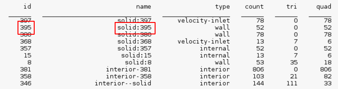
Meshing/mesh/thin-volume-mesh/create() Source face zones(1) [()]source*Source face zones(2) [()]() Target face zones(1) [()]targetTarget face zones(2) [()]Gap Thickness [0]1Number of Divisions [1]5Growth Rate [1]Remesh Overlap Zones? [yes]Start thin-gap mesh:- Create and project nodes and faces on targets…- Project nodes on targets...- Create layer nodes...- Create side quad faces...- Create interior layer cells...- Retriangluate target face zones...- Retriangulate adjacent face zones...Donemesh/zone-names-clean-upCleans up face and cell zone names by removing excessive characters so that the zone names are easier to read. During the course of creating a mesh, various mesh manipulations can cause the face and cell zone names to become cluttered (with colons, dashes, and numbers for example). Using this command, zone names are reduced to include only the original zone prefix, a single colon, and the zone's ID appended to the end.
For example, consider the following listing of zone names:
Upon invoking the command:
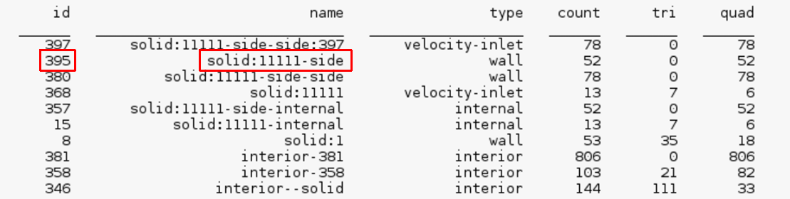
Meshing/mesh> zone-names-clean-up

Cleaning up face and cell zone names...

Meshing/mesh>
The zone listing becomes: