


The model used for the steady-state thermal analysis was created using Ansys Mechanical, generating elements for the starting mesh:
The line bodies representing small copper vias are meshed with LINK33.
Other surface bodies representing the embedded copper in resin and larger vias are meshed with SHELL131.
The laminate and resin solid bodies are meshed using SOLID70. The SOLID70 elements are modified (EMODIF) to create SOLID278 elements to support reinforcing-element generation.
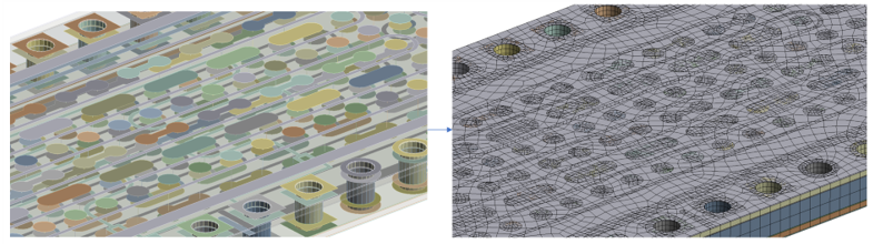
Each of the solid laminate and resin bodies are in default bonded contact with each other at the interfaces, resulting in six bonded contact pairs.
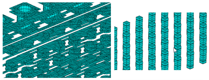
To create the embedded reinforcing elements (REINF264 and REINF265), the LINK33 and SHELL131 elements are modified (EMODIF) to create equivalent MESH200 elements.
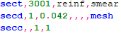
The section properties of the smeared reinforcings with a thickness of 0.042 mm are defined as follows:
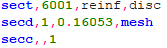
The section properties of the discrete reinforcings with a cross-section area of 0.16053 mm2 are defined as follows:
After selection of appropriate base SOLID278 and MESH200 elements, the reinforcing members are created (EREINF) and shaped (/ESHAPE):
For the downstream structural analysis, the SOLID278 elements are modified (EMODIF) to create equivalent SOLID185 elements. The CONTA174 elements which are part of the thermal bonded contact pairs are also modified to account for the structural solution. The reinforcing REINF264 and REINF265 elements are then reselected to enable their structural degrees of freedom (EREINF).