


The following coordinate system topics are available:
The element coordinate system is used for:
Orthotropic material input
Pressure loading input on certain faces of the surface effect elements
Output of element quantities, such as stresses, strains, and thermal gradients
A default element coordinate system orientation is associated with each element type. In general, these systems are described below. Elements departing from this description have their default element coordinate system orientation described in Element Library.
Element coordinate systems are right-handed, orthogonal systems.
Line elements
The default orientation is generally with the x-axis along the element I-J line.
Solid elements
The default orientation is generally parallel to the global Cartesian coordinate system.
If the program generates SOLID185 or SOLID186 elements during a 2D to 3D analysis (MAP2DTO3D and EEXTRUDE), the element coordinate system's third direction is in the hoop direction about the global Y axis (axisymmetric cases) or in the global Z direction (plane strain cases). For more information, see 2D-to-3D Analysis in the Advanced Analysis Guide.
General axisymmetric elements
The general orientation for SOLID272 and SOLID273 elements is determined by the cylindrical coordinate system, with z and the origin defined via SECTYPE and SECDATA, and θ = 0 on the master plane; the r, θ, and z directions adhere to the right-hand rule. For more information, see General Axisymmetric Elements.
Shell elements
The default orientation for elements SHELL131, SHELL132, SHELL181, SOLSH190, and SHELL281 has the S1 (shell surface coordinate) axis aligned with the first parametric direction of the element at the center of the element. For elements with edges IJ and KL parallel (rectangular or trapezoidal elements), the default orientation (S1 axis) can be interpreted as being parallel to edge IJ (as used by archived elements such as SHELL63).
The element coordinate system orientation is the default orientation for that element type. You can change the orientation via ESYS for area and volume elements, making the orientation parallel to a previously defined local system. For some elements, a KEYOPT selection is available to change the element orientation. If both are specified, the ESYS definition overrides.
The coordinate systems of axisymmetric elements can be rotated about the global Z axis only. General axisymmetric elements, however, can be rotated about any axis.
Shell elements — For shell elements, the ESYS orientation uses the projection of the local system on the shell surface. The element x axis is determined from the projection of the local x axis on the shell surface. If the projection is a point (or the angle between the local x-axis and the normal to the shell is 0° (plus a tolerance of 45°)), the local y axis projection is used for the element x-axis direction. The z and y axes are determined as described for the default orientation.
For non-midside-node shell elements, the projection is evaluated at the element centroid and is assumed constant in direction throughout the element. For midside-node shell elements, the projection is evaluated at each integration point and may vary in direction throughout the element.
Axisymmetric elements — For axisymmetric elements, only rotations in the X-Y plane are valid. Some elements also allow element coordinate system orientations to be defined via user-written subroutines.
General axisymmetric elements — The default element coordinate system can be modified via ESYS, by real constants available for the general axisymmetric solid elements, or by using both ESYS and real constants. For more information, see Using Real Constants to Apply Local Rotations to General Axisymmetric Elements.)
Layered elements — Layered elements use the x axis of the element coordinate system as a base from which to rotate each layer to the layer coordinate system. The layers are rotated by the angles input (SECDATA or RMORE). Material properties, stresses, and strains for layered elements are based on the layer coordinate system, not the element coordinate system.
Cohesive elements — For 3D cohesive elements INTER204 and INTER205, the ESYS orientation uses the projection of the local system on the element neutral surface. The element normal direction is the element x axis. The element y axis is determined from the projection of the local x axis on the neutral surface. If the projection is a point (or the angle between the local x axis and the normal to the element is 0° [plus a tolerance of 45°]), the local y axis projection is used for the element y axis direction. The y and z axes are determined as described for the default orientation. The projection is evaluated at each integration point and may vary in direction throughout the element.
ESYS does not support 2D interface elements INTER202 and INTER203.
All element coordinate systems shown in the element figures assume that no ESYS orientation is specified.
The orientation of output element quantities can be adjusted. See Rotating Results to a Different Coordinate System in the Basic Analysis Guide.
Element coordinate systems can be displayed as a triad via /PSYMB or as an ESYS number (if specified) via /PNUM. Except for general axisymmetric solid elements, triad displays do not include the effects of any real constant angle applied.
For large-deflection analyses, the element coordinate system rotates from the initial orientation described above by the amount of rigid body rotation of the element.
2D and axisymmetric elements operate in the global Cartesian X-Y plane. Accordingly, rotations of the element coordinate system (and/or the coordinate system of any node used by the element) can occur in the X-Y plane only. For example, if a Y-Z rotation is input for such an element, the program issues an error message.
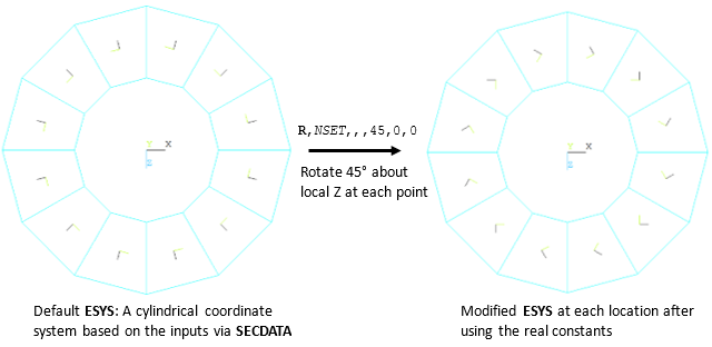
For general axisymmetric solid elements SOLID272 and SOLID273, you can apply rotation angles via real constants to locally rotate the element coordinate system at each integration point. The rotations are applied (in the order shown in the element's Real Constants list) about the default or user-defined element coordinate system at each location. You can use the real constants in combination with ESYS.
The modified element coordinate system can be visualized as a triad (/PSYMB). Triad displays for general axisymmetric elements consider the applied real constant angles for plotting the modified element coordinate system. Use wireframe mode (/DEVICE,VECTOR,ON) to see the element coordinate system more clearly.
Example 1: Modifying the element coordinate system via real constants with the default element coordinate system (ESYS = 0)
Example 2: Modifying the element coordinate system via real constants with a user-defined element coordinate system (ESYS =11)

A few special elements operate solely within the nodal coordinate system:
| COMBIN14 Spring-Damper with KEYOPT(2) = 1, 2, 3, 4, 5, or 6 |
| MATRIX27 Stiffness, Damping, or Mass Matrix |
| COMBIN37 Control Element |
| FLUID38 Dynamic Fluid Coupling |
| COMBIN39 Nonlinear Spring with KEYOPT(4) = 0 |
| COMBIN40 Combination Element |
| TRANS126 Electromechanical Transducer |
| COMBI214 2D Spring-Damper Bearing |
These elements, defined in the nodal coordinate system, allow for easy directional control, especially for the case of two-node elements with coincident nodes.
If UX, UY, or UZ degrees of freedom are being used, the nodes are not coincident, and the load is not acting parallel to the line connecting the two nodes, there is no mechanism for the element to transfer the resulting moment load, resulting in loss of moment equilibrium. The sole exception is MATRIX27, which can include moment coupling when appropriate additional terms are added to the matrix.
You cannot sum nodal force and moment contributions (FSUM) for these elements if the 1D option is activated and nodes are rotated (NROTAT).
If any of the nodes have been rotated (NROTAT), consider the following:
If the nodes of elements containing more than one node are not rotated in precisely the same way, force equilibrium may not be maintained.
Accelerations operate normally in the global Cartesian system. Because no transformation is done between the nodal and global systems, however, the accelerations effectively act on any element mass in the nodal system, giving unexpected results. It is therefore good practice not to apply accelerations when these elements use rotated nodes.
Mass and inertia relief calculations will not be correct.
For homogeneous elements, element solution coordinate systems are generally identical to the nodal or the element coordinate systems adopted by the elements.
For composite elements, solution coordinate systems can be independently defined for different components, such as layers in a layered-shell element (SHELL181) and fibers in a discrete reinforcing element (REINF264). The solution coordinate systems in composite elements are also called layered coordinate systems, and are specifically identified via RSYS,LSYS.
For more information, see Rotating Results to a Different Coordinate System in the Basic Analysis Guide.