


EEXTRUDE
EEXTRUDE, Action, NELEM,
SPACE, DIST,
THETA, TFACT , –,
BCKEY
Extrudes 2D plane elements into 3D solids during a 2D to 3D
analysis.
-
Action Specifies one of the following command behaviors:
AUTO
—
Extrudes plane elements (PLANE182 and PLANE183) based on the KEYOPT(3) setting. Complementary elements are also extruded. (See Notes for more information.) This behavior is the default.
PLANE
—
Extrudes elements in the global Z direction. KEYOPT(3) of the parent plane elements is ignored.
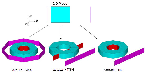
AXIS
—
Extrudes elements about the global Y axis. KEYOPT(3) of the parent plane elements is ignored.
TANGENT
—
Extrudes plane and contact elements about the global Y axis. Target elements are extruded in the global Z direction.
TIRE
—
Extrudes plane and contact elements about the global Y axis in a 360-degree span. Target elements are extruded in the global Z direction if outside the plane elements. Mesh refinement is adapted specifically for tire analysis.
-
NELEM Number of elements to generate in the extruded direction. If you do not specify a number, the program calculates a number automatically based on the average element size and extrusion distance.
-
SPACE Spacing ratio. If positive, this value is the nominal ratio of the last division size to the first division size (if > 1.0, sizes increase, if < 1.0, sizes decrease). If negative, |SPACE| is the nominal ratio of the center division size to the end division size. Default = 1.0 (uniform spacing).
-
DIST Distance to extrude in the global Z direction for the plane strain case (
Action= PLANE). The default is 1.-
THETA Angle (in degrees) depending on
Action:Action= AXIS – Ending angle to extrude about the global Y axis for the axisymmetric case. Default = 360. (The beginning angle is always 0 degrees.)Action= TIRE – Span of the contact patch for mesh refinement. The program generates an abrupt mesh transition from fine to coarse. Default = 0.-
TFACT Factor for increasing the rigid target size. The size of the extruded rigid target elements is determined automatically based on the size of the contact elements. Default = 0.2.
- --
Reserved for future use.
-
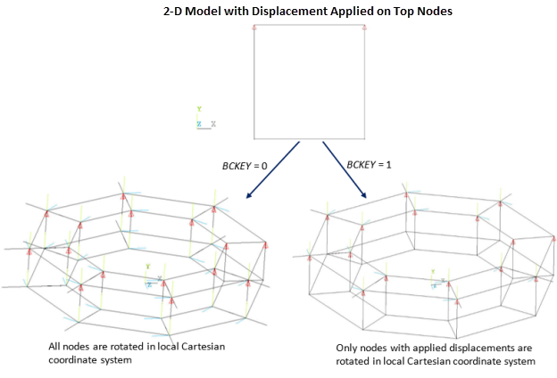
BCKEY Controls the nodal orientation in the third direction and boundary-condition mapping (
Action= AXIS or TIRE only):0 --
—
All nodes are rotated to a local Cartesian coordinate system where X is the radial, Y axial and Z circumferential direction. All loads and displacements are mapped from the 2D model to the 3D model in the local coordinate system.
If applying rotation ROTY in axisymmetric cases with torsion on the 2D model, this value sets UZ = 0 at all corresponding 3D nodes.
This value is the default.
1 --
—
Only nodes with applied loads and/or displacements are rotated to a local Cartesian coordinate system where X is the radial, Y axial and Z circumferential direction. All loads are mapped to the 3D model and all applied displacements are reset to zero.
Notes
The EEXTRUDE command extrudes elements PLANE182 and PLANE183. Complementary elements TARGE169, CONTA172, and REINF263 also extrude. Extrusion operates automatically on elements in the selected element set.
Action = TIRE determines if target elements are in the middle
(rim) part of the model or on the outside (road) part. The middle elements extrude
axisymmetrically about the Y axis, and the outside elements extrude in the Z direction.
If interference exists between road and tire, the command extrudes outside elements within the specified tolerance (SELTOL) in the global Z direction. For more information, see 2D to 3D analysis.
The BCKEY value is valid only within the 2D
to 3D analysis environment (that is, after issuing MAP2DTO3D,START and before
issuing MAP2DTO3D,FINISH).
Use the default BCKEY = 0 setting if you
intend to apply minimal new loads or constraints during the 3D analysis phase; otherwise, set
BCKEY = 1.
For more information, including how boundary conditions and loads are mapped from the 2D model to the 3D model, see 2D-to-3D Analysis in the Advanced Analysis Guide.
This command is valid in the PREP7 (/PREP7) and SOLUTION (/SOLU) processors. Some options are valid within the 2D to 3D analysis environment only (between MAP2DTO3D,START and MAP2DTO3D,FINISH).
Element Behavior
For automatic PLANE182 and PLANE183
extrusion (Action = AUTO), based on the element behavior of the plane
elements, the command performs as follows:
- KEYOPT(3) = 0 --
Plane stress; the element is ignored.
- KEYOPT(3) = 1 --
Axisymmetric; the element is extruded 360 degrees about the Y-axis.
THETAis ignored.- KEYOPT(3) = 2 --
Plane strain (Z strain = 0.0); the element is extruded a unit distance in the global Z direction.
- KEYOPT(3) = 3 --
Plane stress with thickness input; the element is extruded in the Z-direction as specified by the thickness input via a real constant.
- KEYOPT(3) = 5 --
Generalized plane strain; the element is ignored.
- KEYOPT(3) = 6 --
Axisymmetric with torsion; the element is extruded 360 degrees about the Y-axis.
THETAis ignored.
For an axisymmetric extrusion (Action = AUTO with KEYOPT(3) = 1,
Action = AXIS, or Action = TANGENT), the
command merges any nodes within the specified tolerance
(SELTOL,TOLER) of the axis into a single node,
then forms degenerate tetrahedrons, pyramids, or wedges. The default tolerance value is 1.0E-6.
For an axisymmetric extrusion, SHELL208 and SHELL209 will extrude.
You can control shape-checking options via the SHPP command.
The extrusion behavior of accompanying contact (CONTA172) is determined by the plane element settings.
Rigid target (TARGE169) elements are extruded in the global Z direction
unless axisymmetric extrusion (Action = AXIS or
Action = TIRE) is in effect.
Within the 2D to 3D analysis environment (between MAP2DTO3D,START and MAP2DTO3D,FINISH), PLANE182, PLANE183, and associated contact/target/reinforcing elements are supported for the axisymmetric (with or without torsion) and plane-strain options only. For REINF263 reinforcing elements, if the fibers have an orientation angle that causes torsion in an axisymmetric analysis, use the axsiymmetrixc-with-torsion option (KEYOPT(3) = 6) for the base elements. For more information, see 2D-to-3D Analysis Requirements and Limitations in the Advanced Analysis Guide.
2D to 3D Element Pairs
The following table shows each 2D element capable of extrusion and its corresponding post-extrusion 3D element:
| Pre-extrusion 2D Element | Post-extrusion 3D Element |
|---|---|
| PLANE182 | SOLID185 |
| PLANE183 | SOLID186 |
| TARGE169 | TARGE170 |
| CONTA172 | CONTA174 |
| REINF263 | REINF265 |
| SHELL208 | SHELL181 |
| SHELL209 | SHELL281 |
All element properties are also transferred consistently during
extrusion. For example, a  2D element is extruded to a
  3D element, and a mixed u-P 2D element is extruded to a mixed u-P 3D
element. Element and node components are passed over the 3D elements and extruded nodes.
3D element, and a mixed u-P 2D element is extruded to a mixed u-P 3D
element. Element and node components are passed over the 3D elements and extruded nodes.