


Go directly to procedural steps.
The AM process is accomplished through sequential steps that dictate how consecutive solutions are performed in the overall simulation. Minimally, there will always be a build step and usually there is a cooldown step for Thermal-Structural systems. Conceptually, this can be visualized as follows:
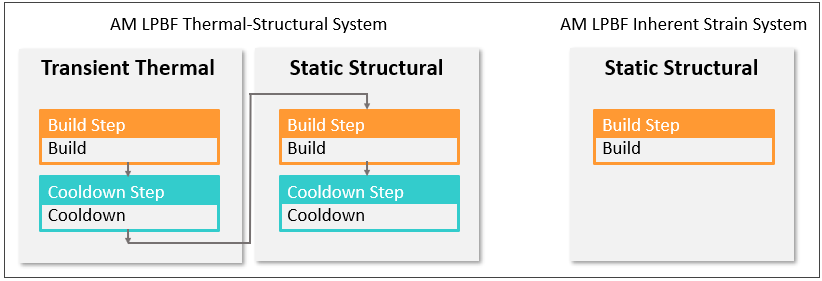
Additional steps may be added to the simulation to account for other phenomena in the AM process, such as the removal of the base plate and/or supports, as shown here for a Thermal-Structural system:
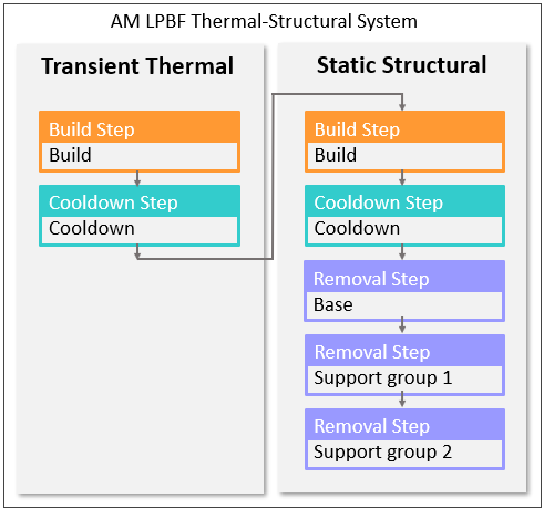
In most cases, base removal is done before support removal. It is important to understand that residual stress and distortion results may be affected by the order in which you remove supports. The Mechanical application can simulate any scenario of support removal.
Other solution steps, such as base unbolting and heat treatment steps and user-defined user steps, may be added before or after removal steps, as shown here:
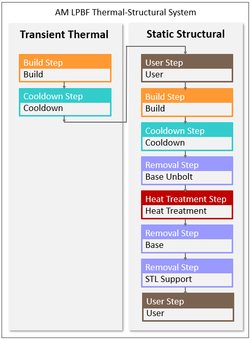
When an additive print is finished, usually the first step is to unbolt the base plate from the machine and transport it for heat treatment or support removal postprocessing. Including this step in the simulation allows more accurate modeling of the deformations in subsequent postprocessing steps. In this step, the constraints for UX, UY, and UZ are removed from the base plate nodes and weak springs are turned on in Analysis Settings. For additional details, see the AMSTEP command. Note that unbolting the base prior to heat treatment can be especially important and is recommended to prevent any artificial stress in the base due to fixed boundary conditions and thermal expansion during heating.
A user step includes a solve execution and may be added at various points in the overall sequence. In the application, a user step effectively leaves the AM simulation environment and enters the usual nonlinear "load step" environment. Any valid loading and load step options may be used. One example of a user step is a bolt pretension step before the build.
Procedural Steps
For AM Process Simulations, the Mechanical application provides an alternative to the ordinary step-manipulation in analysis settings by using a custom worksheet called the AM Process Sequence worksheet, or the sequencer, as we like to call it. Overall viewing and control of the steps in your simulation is done through the sequencer, shown below. You can access the Sequence button only when the AM Process object is selected in the project tree. You can toggle the display on and off using the button any time the AM Process object is selected.
The sequencer enables you to view and change the steps in the simulation. In the screen image below from an LPBF Thermal-Structural system, the steps in the transient thermal analysis and the downstream static structural analysis are conveniently shown side-by-side. Note that unless you use the LPBF Setup Wizard or a Commands object, using the sequencer is the only way to manipulate steps in an AM Process Simulation.
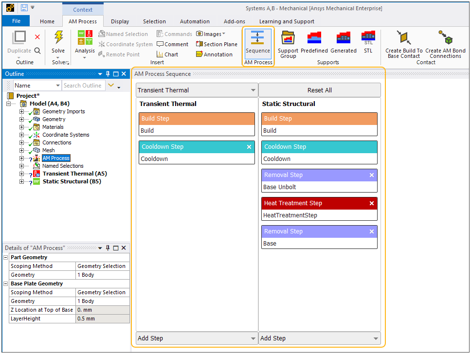
Select the AM Process object and then select the AM Process Sequence option on the context toolbar (or click on Worksheet in the main menu bar).
To add a base unbolting step, click Add Step on the Static Structural side of the worksheet and select Base Unbolt.
To add a heat treatment step, click Add Step on the Static Structural side of the worksheet and select Heat Treatment Step. Additional steps are required to complete the heat treatment step as described in the advanced topic Simulating Heat Treatment after the Build.
To simulate the removal of the base or supports after cooldown or after heat treatment,
Click Add Step at the bottom of the Static Structural side of the worksheet. The dropdown will show the options available for removal, depending on your set-up (Base, Predefined Support, Generated Support, and/or STL Support). You may reorder the steps in the sequence using drag and drop of one step on top of another.
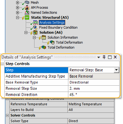
Additional options are available if you choose the base removal step. Under Static Structural, click Analysis Settings in the project tree and select the Removal Step: Base option from the Step drop-down. Choose a Base Removal Type, either Instantaneous or Directional.
Instantaneous: Simulates instantaneous cutoff of all material at the base (bottom layer of elements only).
Directional: Simulates a progressive cutoff of all material at the base (bottom layer of elements only), in which you specify the cut increment and the angular direction for removal from the base.
Removal Step Size: Distance removed in every cut step. Cannot be 0 or a negative number.
Removal Direction: Directional cutoff angle on the X-Y plane as measured from the +X axis. For example, a value of 90 results in a cutoff direction in the +Y direction.
To add a user step to either analysis, click Add Step on the desired side of the worksheet and select User Step. You will then need to specify your step conditions, such as an extra boundary condition, etc. If you want to insert a user step, such as for bolt pretensioning, as the first step in the sequence before the thermal build step, click Add Step and choose User Step Prior to Build.
Note: Advanced Ansys users frequently combine Mechanical APDL commands with the automatic execution of models set up in Mechanical for more precise and custom control over a solution. For example, you may insert a Commands object under the Static Structural or Transient Thermal environment objects in the project tree. In the Commands object Details view, there is a useful option to Issue Solve Command (either Yes (default) or No). It enables users to better control how the commands in the Commands object are processed relative to the step execution in the sequencer.