


On the imported geometry, identify which bodies are associated with the build (part and supports, if any) and the base plate. If your geometry from CAD does not include a base plate, use the Construction Geometry feature to create one.
Procedural Steps
We use the AM Process object in the project tree to establish the options and assumptions appropriate for an additive manufacturing simulation. Note that the AM Process object is available only if you have an Ansys Additive Suite software license with Ansys Mechanical Enterprise or one of the multiphysics bundles. If AM Process is grayed out, check your software license.
If you have inserted an AM custom system—either AM Inherent Strain or AM Thermal-Structural— as the analysis system, or you are working with a model transferred from Additive Prep using the transfer to Workbench feature, then the AM Process object is already added and you can skip the first step in the procedural steps below.
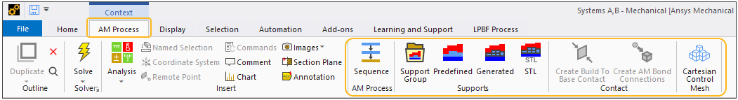
Select the Model object in the project tree, then select the Model contextual tab on the ribbon and then the AM Process option
 in the Define group. Or, right-click the Model object or in the Geometry window and select Insert > AM Process.
Once you insert the AM Process object, certain automatic actions take place. The application automatically:
Displays the AM Process context tab, providing useful shortcut options specific to an AM Process Simulation. These options will be demonstrated in subsequent steps. Note that the AM Process context tab is visible only when the AM Process object in the tree is selected.
Sets Step Controls in an AM Process Sequence worksheet (discussed later) and in Analysis Settings for each analysis.
Suppresses the calculation of thermal fluxes, nodal forces, Euler angles, volume and energy, and other miscellaneous items to reduce the size of the results file. (Set in Analysis Settings for the transient thermal analysis.)
Next you need to identify which bodies are which in the geometry you imported. Select the AM Process object and then:
Select the body or bodies representing the part and the supports that make up the Build Geometry and hit Apply in the Details view. To select a body, be sure that your mode of selection is on body
 (rather than on face, edge, or vertex). Use the
Ctrl key while clicking the left mouse button to select multiple entities (or click, hold,
and drag). Or use named selections as a basis for selection. The build is now shown in red.
(rather than on face, edge, or vertex). Use the
Ctrl key while clicking the left mouse button to select multiple entities (or click, hold,
and drag). Or use named selections as a basis for selection. The build is now shown in red. When selecting supports for identification, select only solid support bodies and not volumeless supports (STL Supports) that may have been imported via transfer from Additive Prep. If you want to have the application create supports automatically, you’ll do that later. For more information about supports, see Identify and/or Generate Supports.
Select the body that is the Base Plate Geometry and hit Apply in the Details view. The base is now shown in blue. (If your imported geometry does not have a base plate, construct one using step 3.)
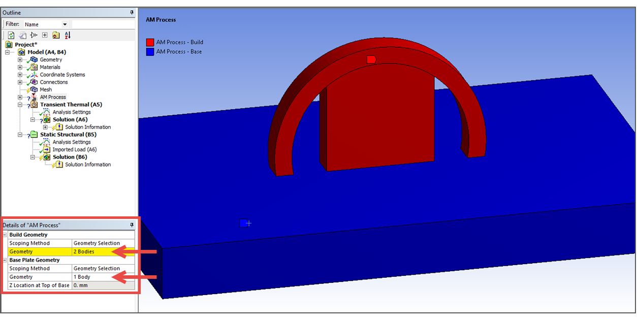
At the bottom of the Details view, the offset of the part from the base is shown as Z Location at Top of Base. This is simply a confirmation of what the Mechanical application reads from the CAD file.
To create the base plate if not imported with the CAD geometry, select the Model object and then:
Right-click the Model object or in the Geometry window and select Insert > Construction Geometry.
Right-click the new Construction Geometry object (under Model) and choose Insert > Solid.
In the Details panel, fields appear for you to enter overall dimensions of the base and coordinates for the center of the top of the base. Enter values for X1, X2, Y1, Y2, Z1 and Z2. An outline is provided to preview the dimensions. Right-click on Solid and select Add to Geometry. See Construction Geometry for more information.
To identify this newly created body as the Base Plate Geometry, highlight the AM Process object, select the new body and hit Apply in the Details view for Base Plate Geometry.