Computing Antenna Parameters
You can Export the calculated antenna parameters and maximum field data to a file. You can also Export Fields for a selected setup in the .csv format or .ffd format. This can be useful for situations when want to share the fields without sharing the model geometry. You can save for use on an antenna parameters Overlay. You can also Export Element Pattern the far field relative to the specified inputs and sources
Note: A Beta feature for HFSS, Hfss Interactive Dialogs, allows you run the Edit Sources dialog and the Antenna Parameters dialog in modeless fashion, that is, if you Edit Sources for magnitide or renormalization, affected Antenna Parameters update. If you edit excitations or ports in the Far Field Setup, or create design variations in Optimetrics, the Edit Source dialog will close.
Case that update in this mode:
-
Infinite sphere setup created, deleted or renamed: Setup Name combo box changes radiation setup.
-
Solution setup created, deleted or renamed.
-
Antenna array setup created or deleted.
-
Source group created, deleted or renamed.
Note: Intrinsic Variation updates as the solution setup changes. Grids of “Antenna Parameters” and “Maximum Field Data” update data as any of the combo box selections changes. The dialog closes if solution type is changed.
Prerequisites
You must have defined at least one radiation or PML boundary in the design for HFSS to compute antenna parameters and maximum field data for the far-field region.
You must have selected Save Fields or Save Radiation Fields only in the Solution setup, and must have generated a solution for a Driven Modal / Driven Terminal / SBR+ / Transient design.
You must have specified and selected Radiation setup.
If the project is a Finite Array, and you want to specify Source Groups, you must previously create them.
Procedure:
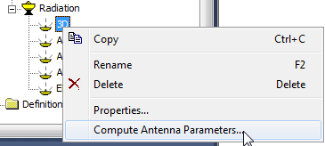
- To select the radiation setup from the
Project tree for a Driven Modal / Driven Terminal / SBR+ / Transient design, right-click the Infinite Sphere
icon in the project tree under Radiation, and then click Compute Antenna Parameters on the shortcut
menu.
Or, to select the radiation setup from a dialog, click HFSS >Radiation>Compute Antenna Max/Params.
The Antenna Parameters
dialog box appears.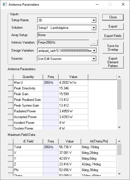
- Select the Radiation Setup Name. A dropdown menu lets you select from available setups.
- For the Solution, select the solution for which you want HFSS to compute antenna parameters.
- If there is an array, select the setup to use.
- For the Intrinsic Variation, select the solved frequency point at which you want HFSS to compute antenna parameters.
- If there is more than one Design Variation available, you can select from the drop-down menu.
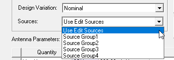
- For Finite Arrays, if you have created one or more source groups, you can select from the drop-downlist.
- The Antenna
Parameters table lets you view computed parameters. If the
design includes ports, the following antenna parameters are listed:
System Gain (if specified in Edit Sources) System Power (typically from an external circuit design and specified in Edit Sources) System efficiency Total Efficiency Warning:The computed values of max U and peak directivity depend on the user-determined set of aspect angles chosen for the computation of the radiated fields. If this set does not encompass the actual peak intensity of the radiated pattern, the displayed results for these three parameters will be inaccurate.
Note:Accepted Power is computed from the raw S-parameter data. Post-processing operations are excluded from the calculation, for example, renormalized S-parameters.
Note:It is important to understand the impact of passive ports (for Transient Network designs or models containing an Array with passive ports) on antenna parameters. For accepted power calculations, passive ports are not included when computing the total power passing through the union of all port surfaces. This means that the passive ports can be viewed as a loss mechanism for the device and it is not equivalent to viewing the passive ports as active ports with zero excitations.
Gain and realized gain are very close to each other when the antenna is matched. However, for designs with a multi-port antenna, gain and realized gain can be different if incident and accepted power are different. There can be a small reflection at the ports and accepted power may still be small if energy injected in one port exits the model through a different port. A review of the S-matrix can show this to be the case. This does not happen in a single port antenna, which is what most users base their expectations on.
When global material environment is a lossy material, antenna parameters such as gain and radiated power are no longer unique because the radiated power depends on the location of the radiation surface since power is lost as the wave travels in the background material.
If the design does not have ports, the following antenna parameters are listed:
- You can view the following maximum far-field
data:
Total
X
Y
Z
Phi (depending on CS Definition in the Far Field Infinite Sphere)
Theta (depending on CS Definition in the Far Field Infinite Sphere)
Azimuth(depending on CS Definition in the Far Field Infinite Sphere) Elevation(depending on CS Definition in the Far Field Infinite Sphere) LHCP
RHCP
Ludwig 3/X dominant
Ludwig 3/Y dominant
Note:When calculating the maximum far-field values, the distance r is factored out of the E-field. Therefore, the units for the maximum field data values are given in volts.
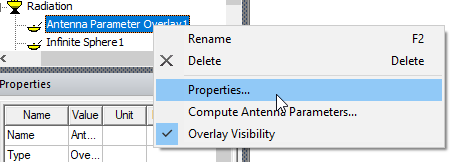
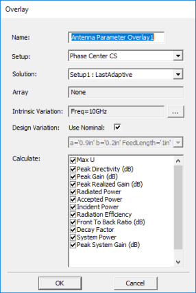
You can right click on an Antenna Parameters Overlay in the Project tree to open a Properties dialog that lets you select a set of the available parameters.