
Exporting Antenna Parameters and Maximum Field Data
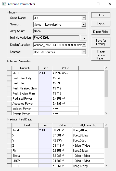
The Antenna Parameters dialog displays the calculated antenna parameters and Maximum Field data for a setup. The dialog also includes a buttons to Export antenna parameters and to Export Fields. The fields can be exported in ffd or .csv format and imported into reporter as a table. You can specify the Setup Name, the Solution, Array Setup (if any), Intrinsic Variation, and Design Variation.
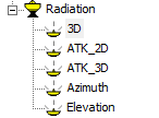
The Setup Name corresponds to the Radiation Setups you create, or that are created by the Antenna Design Kit, for example:
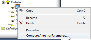
To open the Antenna Parameters dialog box, right-click the Radiation setup for which you want to export parameters or fields, and select Compute Antenna Parameters from the menu
To export the antenna parameters to a text file:
- Click Export on the Antenna Parameters dialog.
This displays a file browser.
- Specify the file name and location (or accept the defaults).
- Click Save.
This saves the text file and closes the browser.
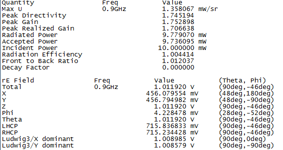
Parameter Format: The parameters are exported to a text file in the following format:
To export the maximum field data to a comma separated format file:
- Click Export Fields on the Antenna Parameters dialog
This displays a file browser
- Specify the file name and location (or accept the defaults)
- Select Save as type as Far Field Data (*.ffd) or Comma Separated (*.csv).
- Click Save.
This saves a text file for the selected Radiation setup in the specified type and closes the browser.
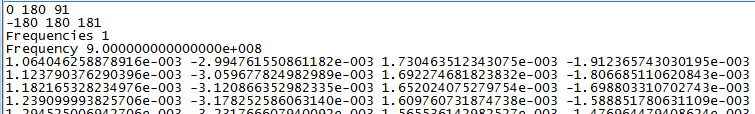
Depending on the kind of Radiation Setup you define, and your Save as type specification, and the coordinate system of the design, the formats will differ. For example for an Infinite Sphere Radiation Setup, using the CS definition as Theta-Phi, will appear as follows:
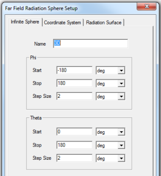
The first lines of the exported .ffd file show the Theta start and stop, then number of steps and then the Phi start and stop values, then number of steps, followed on the next line by the Frequencies number, then on the next line, the first frequency value, followed by field values for that frequency.
If the CS Definition is AzOverEl, or ElOverAz, the first line will state that.
After that identification the next two lines are the Azimuth over Elevation angle definitions (i.e. start, end angle and # of angles). The second angle is always the outer loop, same as for theta phi.
AzOverEl
-90 90 91
-180 180 181
Frequencies 1
Frequency 5.000000000000000e+09
-1.015259849178660e+00 -1.655218649533607e-01 -3.522705268988268e-01 -3.529118467476278e-01
-1.002347316218049e+00 -1.531045876736399e-01 -3.874879909704635e-01 -3.584734921660798e-01
-9.882135774523947e-01 -1.405007760377924e-01 -4.222333606130519e-01 -3.635983928529357e-01
-9.728758526652468e-01 -1.277257858488285e-01 -4.564643039457966e-01 -3.682803049061392e-01
-9.563528285116635e-01 -1.147951814644569e-01 -4.901391158371188e-01 -3.725135241370467e-01
-9.386646357513984e-01 -1.017247168343128e-01 -5.232167687159368e-01 -3.762928930201028e-01
...
If the CS definition in the Infinite Sphere uses ElOverAz, the first line of the .ffd file has a line saying this. After that identification the next two lines are the Elevation over Azimuth angle definitions (i.e. start, end angle and # of angles). The second angle is always the outer loop, same as for theta phi.
ElOverAz
-90 90 91
-180 180 181
Frequencies 1
Frequency 5.000000000000000e+09
-4.637399324983455e-02 2.097570360902490e+00 2.541263616056640e-01 -4.298638962513578e-01
-3.747686134725477e-02 2.081290544083335e+00 2.555899837169427e-01 -5.028061846738747e-01
-2.853406966199131e-02 2.062474995334444e+00 2.567422088036812e-01 -5.751358812117218e-01
-1.955651360818052e-02 2.041146638503657e+00 2.575816330570980e-01 -6.467648632712089e-01
-1.055513095498903e-02 2.017331458908390e+00 2.581072337680435e-01 -7.176058619712824e-01
-1.540888500621979e-03 1.991058471676533e+00 2.583183705730141e-01 -7.875725684672551e-01
7.475231289027627e-03 1.962359686395983e+00 2.582147862343362e-01 -8.565797391048062e-01
...
As another example, consider the following radiation Setup.
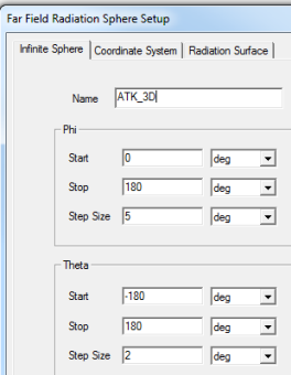
The first lines of the exported .ffd file show the Theta start and stop, then the number of steps and then the Phi start and stop values, then the number of steps, followed on the next line by the Frequencies number, then on the next line, the first frequency value, followed by field values for that frequency.

Near Field Rectangular Setup
For a Near Field Rectangular setup, here are the first six lines of an exported .nfd file. The first line indicates the format of each data line, the 2nd line gives the number of frequencies exported and the 3rd line starts the block for a specific frequency.
For a Near Field Rectangular setup, here are two lines of a .csv file. The 1st line indicates the format of each data line, the 2nd line is a typical data line.

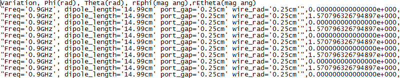
The following Radiation Setup, combined with the .csv format, produces a different set of first lines, and a differently formatted file.
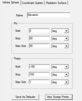
In this .csv file, the first line specifies that the following row includes variation index inclosed in double quotes, then phi value, theta value, then rEPhi (mag ang), rEtheta (mag ang).
Far fields format:
Index, Phi(rad), Theta(rad), rEPhi(mag ang), rETheta(mag ang)
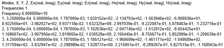
Near fields format in Cartesian Coordinate System:
Index, X, Y, Z, Ex(real, imag), Ey(real, imag), Ez(real, imag), Hx(real, imag), Hy(real, imag), Hz(real, imag)
Near fields format in Spherical Coordinates System:
Index, Theta, Phi, Er(real, imag), Etheta(real, imag), Ephi(real, imag), Hr(real, imag), Htheta(real, imag), Hphi(real, imag)