
Setting up a Far-Field Infinite Sphere
To evaluate radiated fields in the far-field region, you must have Saved Fields in the solution and sweep setups, and set up an infinite sphere that surrounds the radiating object. To plot far-field values across the sphere, you will select the sphere object from the Geometry list in the Traces dialog box when you create a report. To evaluate RCS using a design with an incident plane wave and an SBR+ region, you can also setup an infinite sphere.
- Click HFSS
> Radiation> Insert Far Field Setup>Infinite Sphere or, on an Advanced Solution Setup, Advanced options tab for an HFSS design without SBR+ Hybrid regions, or for use with SBR+ Solver options, Click the Create... button under on the SBR+ Solver options on Hybrid tab of the Solution setup.

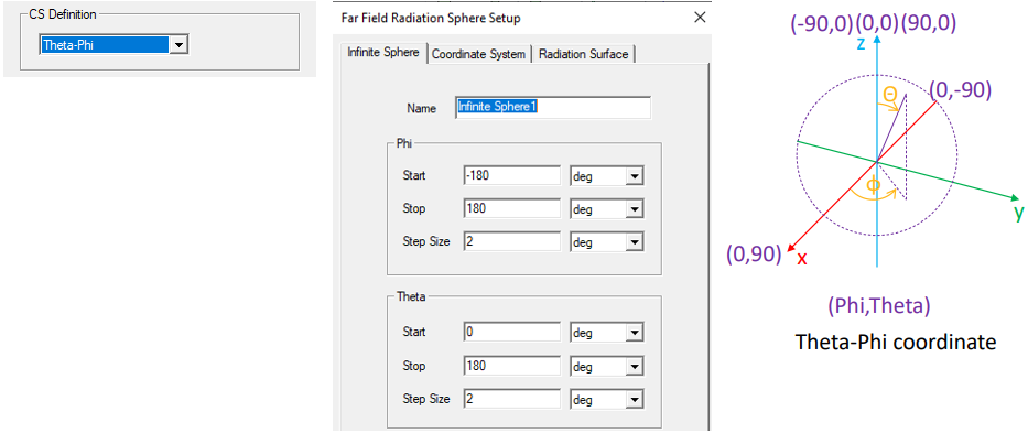
The Far Field Radiation Sphere Setup window appears. Depending on your selections on the Coordinate System tab, the basis will be displayed as Phi Theta, Azimuth Elevation, or Elevation Azimuth. The Default is Phi and Theta. The selection there will also affect display of Maximum Far Field Data if you Computer Antenna Parameters.

- Use the Sphere tab define the Name and sampling in the selected for the far-field sphere.
Specify the sphere's sampling in terms of Start, Stop, and Step Size angles given in radians, degrees, degree seconds or degree minutes.

To verify your settings, use the View Sweep Points button to display a list of the theta and phi sweep points. See Spherical Cross-Sections in the Technical Notes for guidelines for setting phi and theta.

You can use Save as Defaults to set the current values as the default for new near-field sphere setups.
- Use the Coordinate Systems tab to specify the orientation of the sphere as well as the CS System Definition, and the Polarization.

Use global coordinate system is selected by default, but in some cases the orientation of the antenna requires the use of a local coordinate system. In this case, select Use local coordinate system, and choose a local coordinate system that you created previously in the modeler.

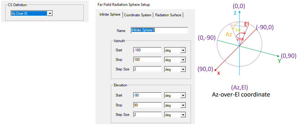
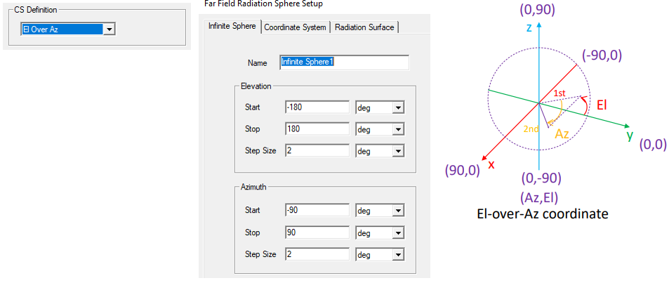
CS Definition: In addition to support Theta-Phi spherical coordinate system, you can select Azimuth over Elevation definition and Elevation over Azimuth definition. Your selection here affects the display on the Infinite Sphere tab. The selection there will also affect display of Maximum Far Field Data if you calculate Computer Antenna Parameters.

For Theta-Phi selection as Coordinate System, the Infinite Sphere setup is as follows.
Azimuth over elevation (Az Over El) has the pole around Y axis while both azimuth and elevation start their 0 deg angle from Z axis. The pole is at elevation angle of –90 deg and 90 deg.
Elevation over azimuth (El Over Az) has the pole around X axis while both azimuth and elevation start their 0 deg angle from X axis. The pole is at azimuth angle of –90 deg and 90 deg.
Polarization: specify the field polarization as Linear, or Slant which decomposes the field into axes rotated with slant angle around the Z axis.

If you select Slant, the field for value and unit menu are enabled. Only CoPolar and CrossPolar values (see Selecting a Far Field Quantity to Plot, Step 4) are affected if Slant polarization is chosen vs. Linear option.

- Use the Radiation Surface tab to select the solved surface from which to calculate radiated fields.
Use Boundary Radiation Surfaces is selected by default, indicating that the radiated fields will be calculated using the assigned radiation or PML surface. For some models you may find it it more efficient and/or accurate to use an interior surface. In this case, select Use Custom Radiation Surface, and choose a face list that you previously created in the modeler.

Do not use a sheet-object based face list as the radiation computation surface.
You can use the Save as Default to set the current values as a default, and the Use Defaults button to use previously saved options.
You must have defined at least one radiation or PML boundary in the design for HFSS to compute far-field quantities, regardless of which radiation surfaces you instruct HFSS to use when calculating the far fields. You do not need to re-solve the problem if you modify radiation surfaces in the Far Field Radiation Sphere Setup window.