
Export Element Pattern from Antenna Parameters
The Antenna Parameters dialog displays the calculated antenna parameters and Maximum Field data for a setup. The dialog also includes a button to Export Element Pattern for the far field relative to the specified inputs and sources. That is, you can specify the Setup Name, the Solution, Array Setup (if any), Intrinsic Variation, Design Variation and Sources.
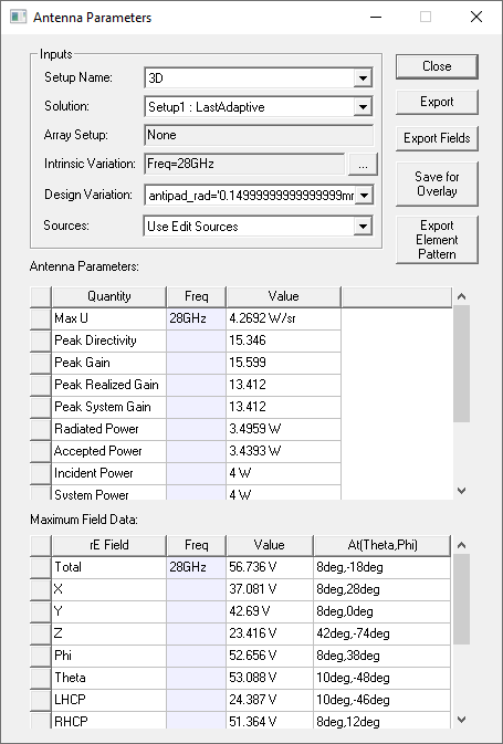
The element pattern export functionality is based on the source group, which means only export the sources contained in the selected source group. To create Source Groups, see Setting up a Source Group. If you select “Use Edit Sources”, then the export includes the sources in Edit Sources dialog box. For each source in the source group, the export provides far field in one ffd file. And each ffd file name is based on the base file name: base file name + “_” + index, where the index is the order of the source shown in Edit Sources dialog box. For clarity, we also export an additional txt file for user, showing the source name to its corresponding ffd file name. The fields are exported in ffd format and can be imported into Reporter as a table.
Since source groups are not supported In Transient solution type, clicking Export Element Pattern exports all the sources in Edit Sources dialog (i.e. equivalent with “Use Edit Sources”).
The exported far field data in ffd file is based on the conditions when activated source(s) are excited with 1.0 magnitude in SI units and 0.0 phase, and inactivated sources have 0.0 magnitude and 0.0 phase.
In Driven Terminal solution types, if a source is terminated, no far field file will be exported for it. The other exported sources are affected by the resistance and reactance of the terminated source.
Export Element Pattern respects the phase center setting, if used. (For the Set Far Field Phase Center command, see Link from Driven Modal Design to SBR+ Design.)
If a per-port phase center is defined, for a finite array design, the phase center coordinate system (CS) will shift according to the unit cell location (also the same to SBR+ link). If a global phase center is defined, all the ports will use that CS for export. No phase center CS shift will happen.
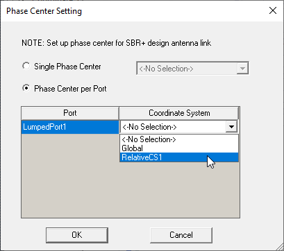
If the phase center setting is not defined, then the export will use the reference coordinate system in the infinite sphere setup, and there will not be an automatic shift for finite array design for unit cells. So basically all the ports will use the same CS for phase center.
Procedure for Export Element Pattern
The Setup Name corresponds to the Radiation Setups you create, or that are created by the Antenna Design Kit, for example:
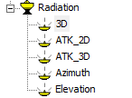
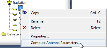
To open the Antenna Parameters dialog box, right-click the Radiation setup for which you want to export parameters or fields, and select Compute Antenna Parameters from the menu
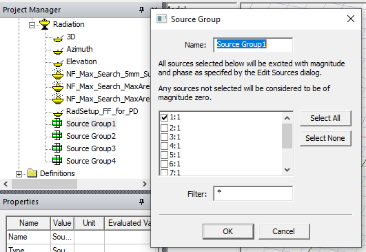
Select the desired source group via combo-box named as “Sources”.
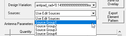
The element pattern export functionality is based on the source group, which means we only export the sources contained in the selected source group. If user selects “Use Edit Sources”, then we will export all the sources in the Edit Sources dialog.
To export the Element patterns to an .ffd text file:
- Click Export Element Pattern on the Antenna Parameters dialog
This displays a file browser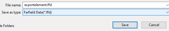
- Specify the file name and location (or accept the defaults). Save as type is Far Field Data (*.ffd).
- Click Save.
This saves a text file for the selected Radiation setup in the specified type and closes the browser.
For each source in the source group, we export its far field in one ffd file. And each ffd file name is based on the base file name: base file name + “_” + index, where the index is the order of the source shown in Edit Sources dialog box. For clarity, we also export an additional txt file for user.
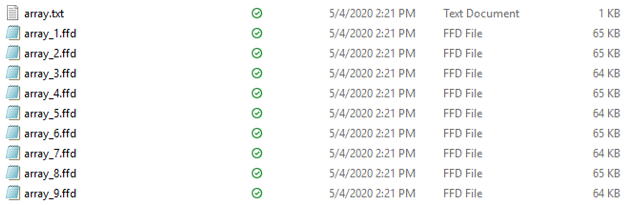
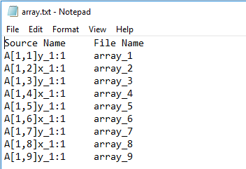
This figure shows the content of an array.txt file. It shows the source name to its corresponding ffd file name
The content in each source’s ffd file is the far field data on an infinite sphere. If the infinite sphere setup is defined with the CS Definition as Theta-Phi, the first two lines are the theta, phi angle definitions (i.e. start, end angle and # of angles). Each data line contains the eTheta and ePhi in complex #. It has the same format as the far field data file produced by Export Fields in Antenna Parameters dialog.
0 180 91
-180 180 181
Frequencies 1
Frequency 5.000000000000000e+09
7.766368308173010e+00 9.532038867040301e+00 8.755867923644274e-01 2.563969382196918e-01
7.792194784812795e+00 9.535180330609501e+00 6.040110633865901e-01 -7.642261087584279e-02
7.808527672402878e+00 9.526704645727785e+00 3.316994399687877e-01 -4.091490507920261e-01
7.815347071835619e+00 9.506622138711604e+00 5.898369187776575e-02 -7.413770056143987e-01
7.812644674723257e+00 9.474957277002284e+00 -2.138039187560649e-01 -1.072701706755799e+00
7.800423773520401e+00 9.431748639356224e+00 -4.863310422488643e-01 -1.402719486104554e+00
...
If the CS definition in the Infinite Sphere uses AzOverEl, the first line of the .ffd file has a line saying this. After that identification the next two lines are the Azimuth over Elevation angle definitions (i.e. start, end angle and # of angles). The second angle is always the outer loop, same as for theta phi.
AzOverEl
-90 90 91
-180 180 181
Frequencies 1
Frequency 5.000000000000000e+09
-1.015259849178660e+00 -1.655218649533607e-01 -3.522705268988268e-01 -3.529118467476278e-01
-1.002347316218049e+00 -1.531045876736399e-01 -3.874879909704635e-01 -3.584734921660798e-01
-9.882135774523947e-01 -1.405007760377924e-01 -4.222333606130519e-01 -3.635983928529357e-01
-9.728758526652468e-01 -1.277257858488285e-01 -4.564643039457966e-01 -3.682803049061392e-01
-9.563528285116635e-01 -1.147951814644569e-01 -4.901391158371188e-01 -3.725135241370467e-01
-9.386646357513984e-01 -1.017247168343128e-01 -5.232167687159368e-01 -3.762928930201028e-01
...
If the CS definition in the Infinite Sphere uses ElOverAz, the first line of the .ffd file has a line saying this. After that identification the next two lines are the Elevation over Azimuth angle definitions (i.e. start, end angle and # of angles). The second angle is always the outer loop, same as for theta phi.
ElOverAz
-90 90 91
-180 180 181
Frequencies 1
Frequency 5.000000000000000e+09
-4.637399324983455e-02 2.097570360902490e+00 2.541263616056640e-01 -4.298638962513578e-01
-3.747686134725477e-02 2.081290544083335e+00 2.555899837169427e-01 -5.028061846738747e-01
-2.853406966199131e-02 2.062474995334444e+00 2.567422088036812e-01 -5.751358812117218e-01
-1.955651360818052e-02 2.041146638503657e+00 2.575816330570980e-01 -6.467648632712089e-01
-1.055513095498903e-02 2.017331458908390e+00 2.581072337680435e-01 -7.176058619712824e-01
-1.540888500621979e-03 1.991058471676533e+00 2.583183705730141e-01 -7.875725684672551e-01
7.475231289027627e-03 1.962359686395983e+00 2.582147862343362e-01 -8.565797391048062e-01
...