
Scaling Sources for HFSS
- Click HFSS >Fields>Edit Sources.
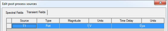
The Edit post process sources dialog
box appears For modal projects, the Spectral fields tab shows the following
column headings.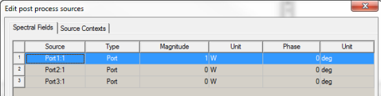
If the project contains symmetry planes, the dialog includes a reminder that you may need to adjust the scaling factor accordingly.
For HFSS Terminal solutions, you can select
a Terminal Excitation Type as Incident Voltage or Total Voltage.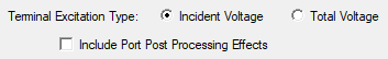
Selecting Total Voltage adds more columns to the
table.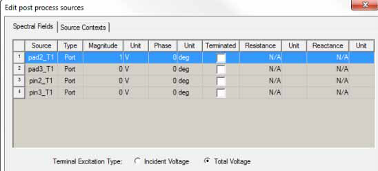
Note that in the modal case a unit stimulation means 1 Watt of incident power at the port; in the terminal case a unit stimulation means 1 volt of total voltage at the terminal. After converting the voltage stimulation to the equivalent power stimulation the antenna results agree perfectly. In particular, the "ratioed" antenna parameters such as gain, directivity, and efficiency agree between the modal and terminal projects, while absolute antenna quantities such as incident power, accepted power may initially appear different. This is a direct result of the difference in edit-sources stimulations in the two types of projects.
You can scale the sources individually through the source table in the Edit post processing sources dialog box, or you can Save to File or Load From File, using the .csv format or tab delimited data (.txt) format. This feature can help for projects with many sources. The steps below describe how to directly edit the source table.
- Select the source whose magnitude and phase you want to scale.
- In the Magnitude
text box, enter the magnitude you want. Design variables
can be used as source scalings.
Note:
You may not enter a negative voltage. To obtain the equivalent of a negative magnitude, add or subtract 180 degrees from the phase value.
If you use a design variable as a scaling factor note that solutions are invalidated if the variable is changed.
If the model contains symmetry planes, the Edit Sources dialog alerts you that you may need to adjust the scaling factor accordingly.
At least one source should be excited (non-zero). If you set all sources to zero, you will receive a warning, but the values do go through.
- In the Phase text box, enter the new phase for the source.
The phase of the source is changed by the value that you enter.
- Optionally, if your solution type is driven terminal, you may specify a complex reference impedance:
- For the selected terminal, select Terminated.
This disables the values to the left of the check box, and enables the Resistance and Reactance text boxes. Use the scroll bar to view them.
- Enter the Resistance and the Reactance and select the units. Ohms is the default.
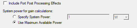
- By option, you can click a check box to
Include Post Processing Effects. Note that the post processing
effect has no impact on the impedance of a terminated port.
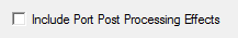
Checking this box also enables an Apply button.
- For gain calculations, you can check whether to Specify System Power or Use Maximum Available Power. Selecting Specify System Power enables a field for value for power and select units. Use Maximum Available Power provides a default. The system power typically comes from an external circuit (e.g., a Circuit project), and is used in computing System Realized Gain in antenna parameters and System Gain in far field reports.
You can specify incident power for gain calculations as a function of frequency, for example, pwl(ds1,freq).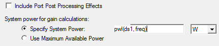
- For HFSS, if an incident wave is present,
use the radio buttons at the bottom of the panel to select one of the
following field types to use:
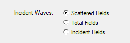
Scattered Fields
The differential field formed by subtracting the incident field from the total field.
Total Fields
The physically measurable field that exists with the model present and a non-zero incident field.
Incident Fields
The plane-wave field that would exist in the absence of the model.
For the total field of a Floquet port also chosen as the source in Edit post process sources, you should always select Scattering Fields as the 2D surface fields, rather than the Total Fields. The Floquet ports are added in the far field calculation when the Solution setup Save radiated fields only option is checked. However, if you then create custom radiation surfaces, the 3D volume total fields are used in the calculations. In this specific situation, this causes inconsistent results between the default radiation surfaces the custom surfaces. Otherwise, there is no difference between scattering fields and total fields. since "total fields" = "incident fields (source fields)" + "Scattering fields".
For HFSS with SBR+ designs that include ports, incident waves, or linked incident waves, the Field Type options take this form: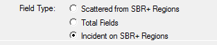
In the case of SBR+ with incident waves, the field type can only be Scattered from SBR+ Regions. For SBR+ designs with Port sources or linked incident waves, you can select from all three types.
For Eigenmode solutions, the Edit post process sources dialog displays a Spectral Fields tab and radio buttons for selecting as the Eigenmode Excitation Type, either Peak Electric Field or Stored Energy.

For Stored Energy, the table lists Magnitude and Unit as editable fields. For Peak Electric field, the editable fields are Magnitude, Unit, Phase, and Unit.
- The Source Contexts tab lets you select the sources to use as context when you create radiated fields reports.
- Click OK to apply the changes and close the dialog box, or click Apply to view the changes without closing the dialog.
The magnitude and phase are assigned to the selected excitation.
When you scale an excitation, keep in mind that the original value of the excitation remains unchanged.