


A spatially varying load or displacement has a variable magnitude in a single coordinate direction (x, y, or z). The following load and displacement types qualify as varying loads and varying displacements, and can also be a function of time.
Pressure (In a Normal direction only during a Static Structural analysis )
Line Pressure (In a Tangential direction only during Static Structural analysis)
Pipe Pressure (Static Structural analysis only)
Pipe Temperature (Static Structural analysis only)
Convection (Thermal analysis only)
Heat Flux (Thermal analysis only)
Temperature (Thermal analysis only)
Thermal Condition (Static Structural analysis only)
Displacement (For Faces, Edges, or Vertices during a Static Structural analysis.)
Note: If you select multiple Convection load objects that include variable data, the application displays only one solid color for the scoped entities.
For spatial varying loads and displacements, the spatial Independent Variable property uses the origin of the coordinate system for its calculations and therefore it does not affect the direction of the load or displacement. To apply a spatial varying load or displacement, you must first generate the mesh, and then specify the Magnitude property of the variable load, or the load input, as Tabular or as a Function and then specify the desired coordinate (X, Y, or Z) for the Independent Variable property.
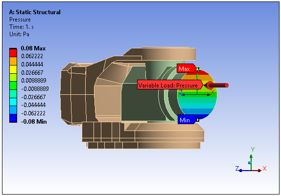
Once specified, and given that you have generated the mesh on the model, variable loading conditions display as contours. For convection loads and loads specified using the General Axisymmetric feature, varying loads are displayed in purple and there is an annotation in the Geometry window that indicates the load as a "Variable Load."
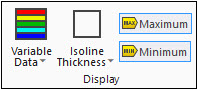
And, the Display group (shown below) becomes visible on the Environment Context Tab. From this group, the Variable Data drop-down menu provides the display options: , , and . When you select the display option, the Isoline Thickness drop-down menu enables you to change the thickness of the displayed lines. Options include (default), , or . The toolbar also contains options to display the Maximum and Minimum values of the spatial varying load or displacement. You can toggle these min/max options on (default) and off.
Important: If you have a model with a large number of parts/bodies, there is a performance-based display preference available for displaying variable load contours. In the Options dialog, under the Graphics category, the Varying Loads (Optimization Options) control provides the options (default) and . The option displays discrete points on the model, based on legend colors, of the load variation. This option provides significantly faster redrawing times that is beneficial for large models. The setting displays variable load contours normally.