When you analyze electric machines and the effects of electromagnetic forces, noise and vibration is a primary consideration.
Ansys Workbench enables you to evaluate Equivalent Radiated Power (ERP) Waterfall diagrams. ERP diagrams provide efficient results that you can use to analyze structure vibration for a range of rotating conditions and frequencies.
For a more in-depth acoustic analysis, you can generate waterfall diagrams for Far-field Sound Power Level and Far-field Sound Pressure Level Microphone results. See the Adding an Acoustics Analysis topic at the end of the section for the steps to incorporate this analysis type.
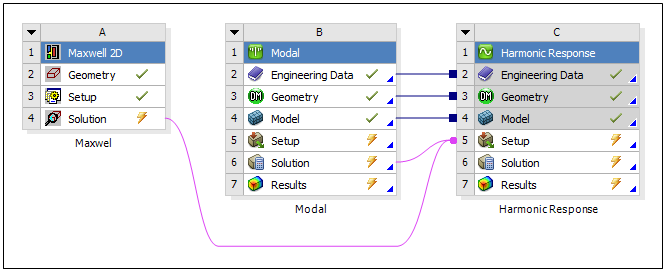
This section examines the workflows to simulate electromagnetic forces for rotational velocities as well as the steps to transfer the data to a downstream Ansys Mechanical (frequency domain) Harmonic Response and Harmonic Acoustics systems. Example system configurations are show below.
Also note that you can use the operating conditions from your Harmonic Response analysis for Acoustics analyses. This can include all or selected (more critical) operating conditions.
Maxwell Parametric Study
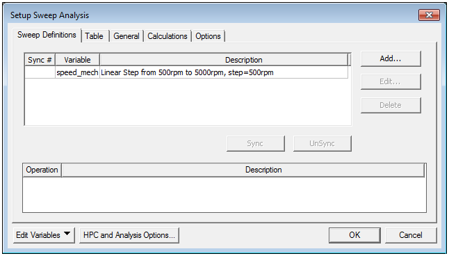
You can use a Maxwell analysis (2D or 3D) that includes several rotational velocities to analyze the overall operating conditions of a Mechanical system. You can use Maxwell to calculate the electromagnetic forces for each of the RPM (Rotations Per Minute). As depicted in the following dialog, you can create a DesignXplorer setup in Maxwell using the rotational velocity as a variable for the Sweep Definitions. See the Maxwell Help for more information.
Import Loading
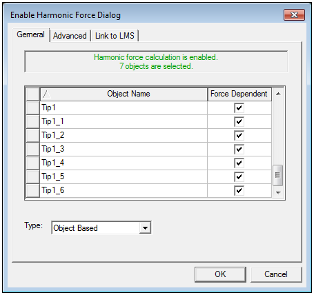
Based on the option Type (Object Based or Mesh Based) selected in Enable Harmonic Force Calculation dialog in Maxwell, you send either integrated force per object or spatially varying data are to Mechanical:
Object Based: This type calculates remote forces and moments on each selected object and imports frequency varying Remote Forces and Moments to Mechanical.
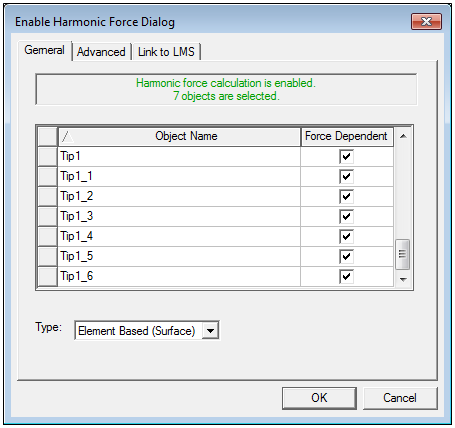
Mesh Based (Surface): This type calculates forces on mesh entities for the selected objects, converted to frequency domain, and imports spatially varying Surface Force Density loads to Mechanical.
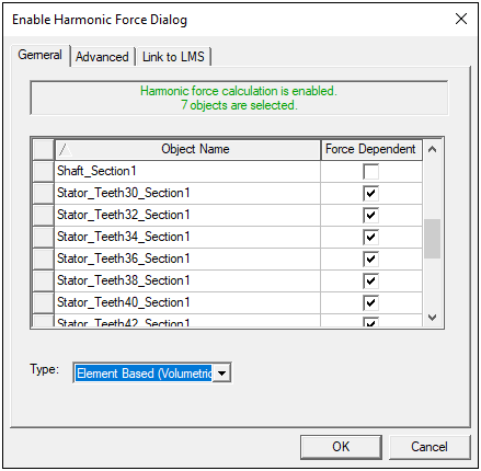
Mesh Based (Volume): It type calculates forces on mesh entities for the selected objects, converted to frequency domain, and imports spatially varying Body Force Density loads to Mechanical.
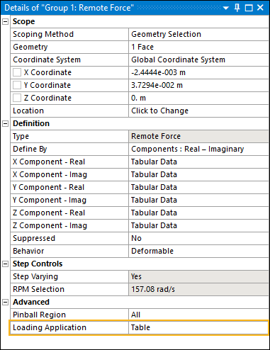
Object Based - Remote Force and Moment
For the option when you import your Maxwell analysis into Mechanical, the application automatically creates an Imported Remote Loads object. The context (right-click) menu for this object provides the option . When you execute this option, the application automatically imports the remote forces and moments from Maxwell and maps the loads to the geometric entities on the model.
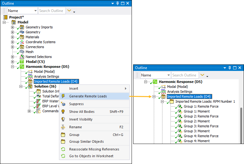
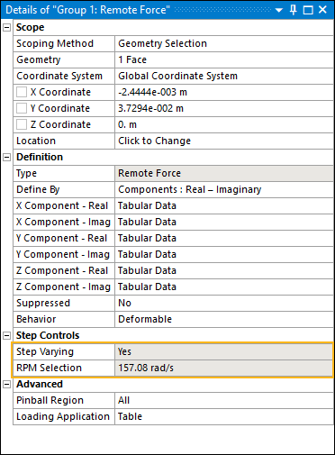
For each RPM variation solved in Maxwell, Mechanical creates a folder containing the forces associated with the rotational velocity. Here are the Details properties for a selected (imported) Remote Force. You can see the load is specified as a varying load (Step Varying property) and it includes a load value (RPM Selection property).
Mesh Based - Surface Force Density
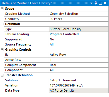
For the option when you import your Maxwell analysis into Mechanical, the application automatically creates an Imported Load object. The context (right-click) menu for this object provides the option . When you execute this option, the application automatically imports the Surface Force Density loads from Maxwell and maps the loads to the geometric entities on the model.
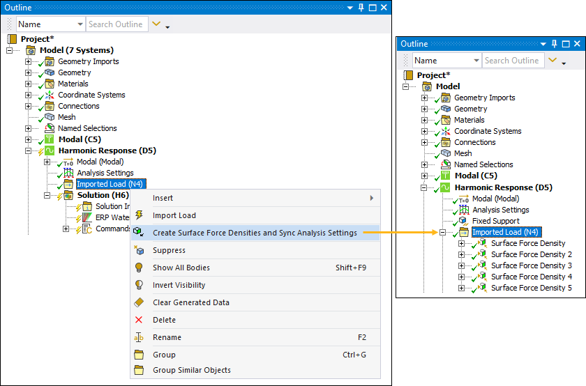
The application creates a Surface Force Density object for each RPM variation created in Maxwell.
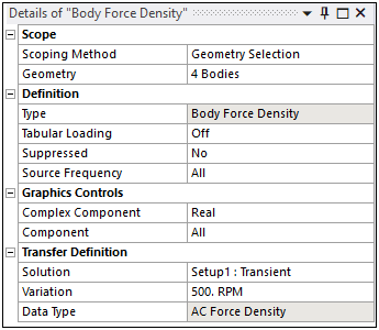
Mesh Based - Body Force Density
When you import your Maxwell analysis into Mechanical, the application automatically creates an Imported Load object. The context (right-click) menu for this object provides the option Create Body Force Densities and Sync Analysis Settings. When you execute this option, the application automatically imports the Body Force Density loads from Maxwell and maps the loads to the geometric entities on the model.
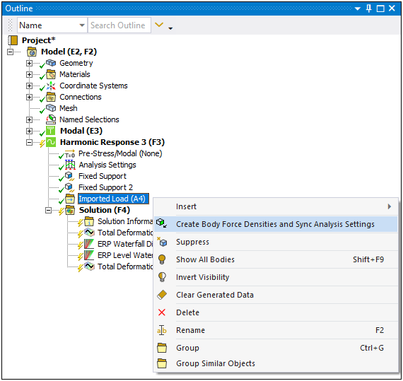
The application creates a Body Force Density object for each RPM variation created in Maxwell.
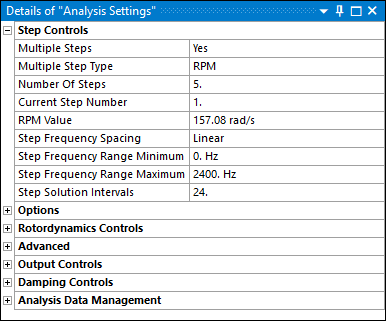
Define Analysis Settings
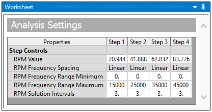
When your Maxwell load data includes multiple RPM conditions, the application automatically reflects the RPM conditions as load steps in the Step Controls category of the Analysis Settings of your downstream, Harmonic Response analysis. You can modify these RPMs (individually) using the Step Controls category.
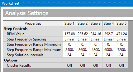
You can also modify the RPM Step Controls using the Worksheet.
Harmonic Solution Method
The application supports the Maxwell import scenarios both the and Solution Method in your Harmonic Response analysis. Each of these methods supports constant loading conditions that you may apply (on each step) in addition to the imported RPM varying loads, that the application applies on a per step basis. For example, you want to add loads in addition to the imported electromagnetic forces. You may wish to add loading conditions to consider other noise sources, such as those generated by bearings or aerodynamic forces.
For the method, by default, the application defines the remote forces using the option for the Loading Application property to improve solution performance.
Also note that when you import Surface Force Densities, you can improve solution performance by initiating the Expand Results From property (Output Controls) by setting either the Stress, Strain, or Calculate Reactions properties to Yes.
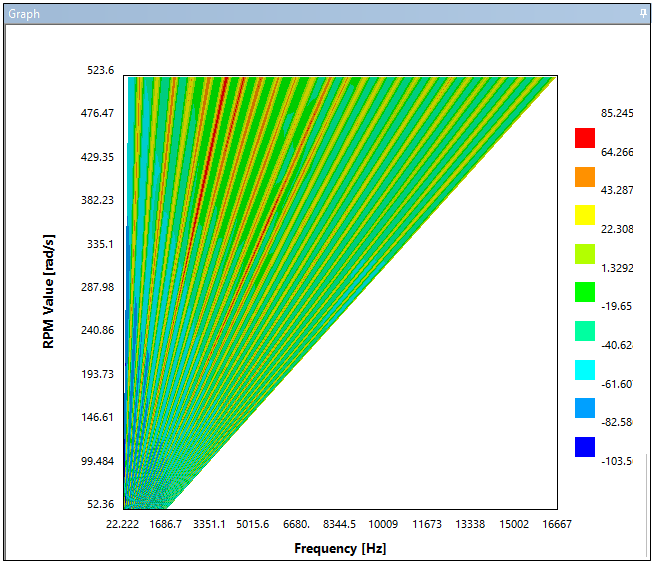
ERP Waterfall Diagram
The Equivalent Radiated Power (ERP) waterfall diagram results provide a global acoustic signature based on the selected radiating faces. The application displays this result in two forms: (1) using polylines for each RPM case or (2) on a 2D color map, as illustrated here. This result enables you to detect the most critical operational conditions (RPM and Frequency) analyzed with additional detail in a downstream Harmonic Acoustics analysis.
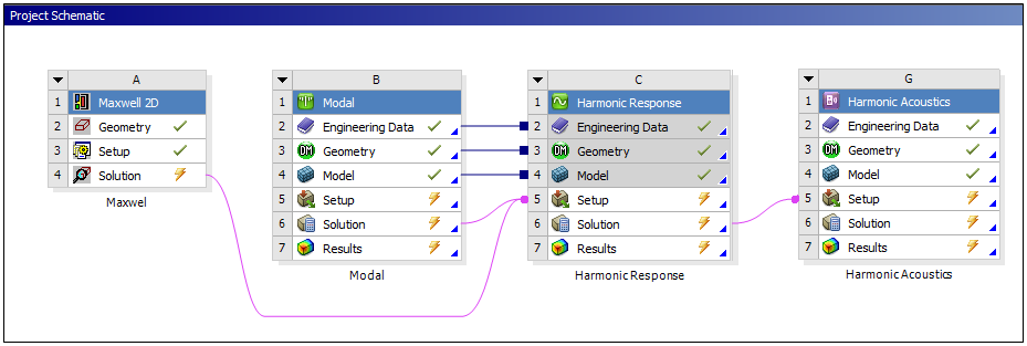
Adding an Acoustics Analysis
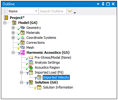
You can examine the acoustics of your structural vibrations by adding a Harmonic Acoustics analysis to your NVH simulation. As illustrated, you insert a Harmonic Acoustics into the project as a downstream system.
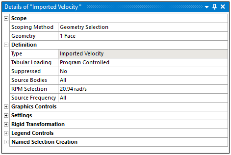
Once opened in Mechanical, the application automatically creates an Imported Load object. By default, the application inserts a Imported Velocity object.
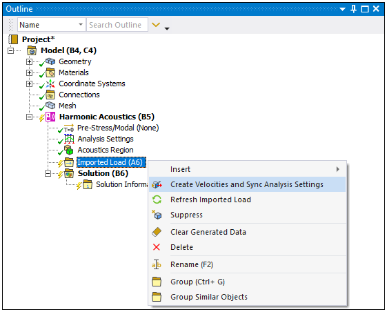
You can add Imported Velocity objects by right-clicking on the Imported Load folder and selecting > or you can select the option to import and map all of the velocity loads available in the upstream system.
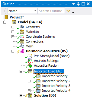
The application creates an Imported Velocity object for each RPM imported from the upstream Harmonic Response analysis.
When you import multiple RPMs, the application automatically reflects the RPM conditions as load steps in the Step Controls category (that automatically displays in the Worksheet) of the Analysis Settings of your downstream Harmonic Acoustics analysis. This behavior is similar to the Step Controls of a Harmonic Response system. See the Step Controls for Harmonic Analysis Types section for more information.
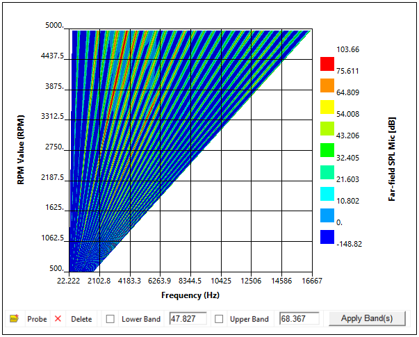
Result Diagrams
Once you complete your analysis, the result options Far-field Sound Power Level Waterfall Diagram and Far-field SPL Mic Waterfall Diagram enable you to analyze the acoustic behavior for the entire range of RPMs and frequencies so that you can detect the most critical situations. An example is illustrated below. See the Acoustic Waterfall Diagrams for additional information.