


The Pre-Meshed Cyclic Region is a symmetry option that does process the specified selections for the Low Boundary and High Boundary properties. Normally, the application uses these selections to specify the nodes to write cyclic constraint equations; however, this object instead uses the cycle angle to determine the nodes used to create cyclic symmetry.
This option is used to define cyclic symmetry for cases where you cannot generate a matched mesh using the low and high boundaries. Not being able to match the mesh is often the case when you import mesh from an external source, such as Model Assembly, External Model, or ACP. To match your mesh, the Pre-Meshed Cyclic Region enables you to select the exact orientation of nodal coordinate systems on the sector boundaries. And the feature includes the additional property Relative Distance Tolerance that enables you to modify the automatic sector boundary detection of low and high boundary.
Note:
When the solver detects matching node pairs, you can view the matched nodes using the option of the Display property (FE Connection Visibility category) of the Solution Information object.
This feature instructs the application to find all nodes separated by the sector angle and apply the cyclic boundary condition to them. Nodes separated by the sector angle cannot be excluded from being part of the cyclic symmetry condition.
Requirements
Note the following:
This symmetry option inherits the limitations and restrictions of the Cyclic Region. For consistency with the cyclic symmetry solution method, some restrictions apply when defining the orientations for nodes on the sector boundaries. Refer to the Cyclic Region section for additional information.
The Number of Sectors property requires an entry (a natural number, N>2).
Loads and supports are assumed to have the same spatial relation with respect to the cyclic axis in all sectors. Also the loads and supports defined in Mechanical are applied for each and every sector by Mechanical APDL.
Applying Constraints
Unlike the use of the Cyclic Region object, the application will not attempt to convert supports to nodal DOF constraints on either of the sector boundaries (low or high). This means that any support that depends on these conversions should not contain faces, edges, or vertices that touch the sector boundaries. Exempt from this requirement are:
Nodal Displacements and Nodal Orientations can be used to manually adjust any node-based degree-of-freedom constraints on problematic topologies so they become consistent with both the loading conditions and the cyclic symmetry method. The solver can be used to automatically assign these DOFs (Set the Boundary DOF Orientation property to ), but then Nodal Displacements should be used with caution because final DOF directions may not be known prior to solution. You can use Nodal Triads to verify how Mechanical APDL orients the nodes.
To manually prescribe orientations on the sector boundary, set the Boundary DOF Orientation property to , and then apply any Nodal Orientations necessary to meet restrictions posed by the cyclic symmetry method. Review the example provided later in this section for additional information.
Nodal Orientation Requirements
By default, all nodes are oriented using the Global Coordinate System. To orient the nodal coordinate systems in a manner consistent with cyclic symmetry, the following conditions are required:
- Nodes on Sector Boundaries
Nodes on sector boundaries are free to orient with any direction as long as each node pair meets this condition: Nodal orientations on the low and high sector differ by a rotation of exactly 360°/N about the cyclic axis. The difference must be in phase with the cyclic axis. For example, if the sector angle is 90°, then the axis for a node must be obtained by rotating the coordinate system for the corresponding node on the low boundary by +90° around the cyclic axis.
When Boundary DOF Orientation is set to , Mechanical APDL typically aligns the nodal x axis radially, y tangentially and z axially with respect to the cyclic axis.
- Nodes on the Cyclic Axis
If your model contains nodes on the cyclic axis, they require special treatment. The nodes’ orientation must produce an axis which is aligned with the cyclic axis.
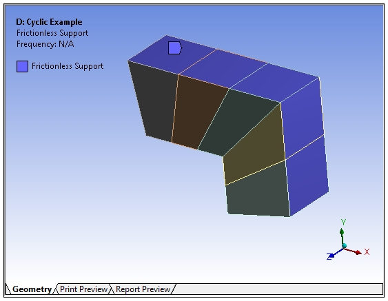
Example: Applying a Frictionless Support Manually via Direct FE
This example demonstrates how to apply the equivalent of a Frictionless Support using Nodal Displacements and Nodal Orientations on a quarter section of a cyclically symmetric model using a Pre-Meshed Cyclic Region. The first illustration below depicts a Frictionless Support applied to the exterior faces of a symmetry model. Because this boundary condition shares topology with sector boundaries, it will not solve.
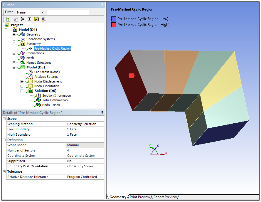
The second image illustrates a defined Pre-Meshed Cyclic Region object. It selects the same low/high face selections you would use for a
Cyclic Region. It is a quarter-section so the Number of Sectors property is set to 4 and the
Boundary DOF Orientation property is set to .
|
|
|
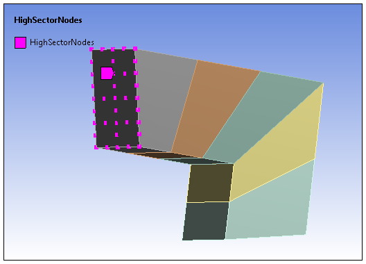
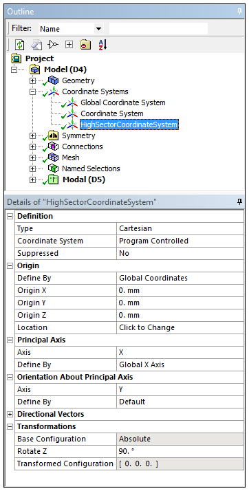
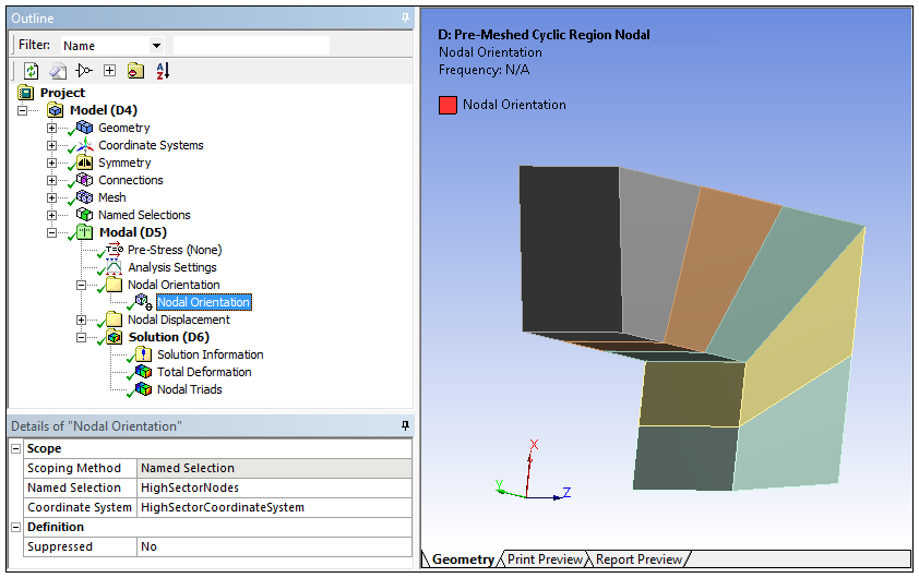
To meet the nodal orientation requirements, we need to rotate the high boundary nodes. That means we first need to create a node-based Named Selection of the high sector node ("HighSectorNodes" illustrated below). Then, to achieve the desired orientation, we need to create Cartesian Coordinate System. This coordinate system requires a rotational transformation about the z axis so that we can rotate the nodes 90° (360°/4 = 90°). Below we have created the necessary coordinate system, "HighSectorCoordinateSystem" that includes the needed rotation (Rotate Z property) about the z axis.
|
|
|
Now, a Nodal Orientation object is inserted using the coordinate system and the node-based Named Selection, to meet the nodal orientation conditions required by the cyclic symmetry method.
Understanding Frictionless Support
As with all boundary conditions, a Frictionless Support applies displacements to nodes in their nodal coordinate system. In particular, a Frictionless Support applies displacements which fix the nodes in the direction of the normal of the element faces. As stated above, in this example we are applying the equivalent of a Frictionless Support for several exterior faces. Of these exterior faces, two are normal to the global +X, and three are normal to the global +Y.
Oriented +X Normal
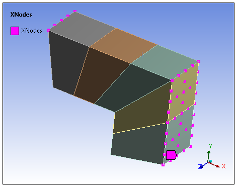
The intent is to fix these nodes in global X. The nodes on these faces have no Nodal Orientation applied on them, so they are oriented with the Global Coordinate System. A Nodal Displacement of X=0 is required for these nodes (Requirement 1 - XNodes).
Oriented +Y Normal
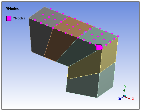
The intent is to fix these nodes in global Y. The majority of the nodes on these faces have no Nodal Orientation applied on them. A Nodal Displacement of Y=0 is required for these nodes (Requirement 2 - YNodes). The orientation of the remaining nodes on the edge of the high sector have been specified by the Nodal Orientation applied above. The Global Y for these nodes is equal to their Nodal X. Therefore, a Nodal Displacement of X=0 is required for these nodes (Requirement 3 - XNodes).
The node-based Named Selections needed to meet our requirements are illustrated below.
|
|
|
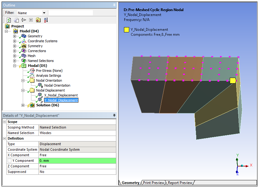
Applying Nodal Displacements
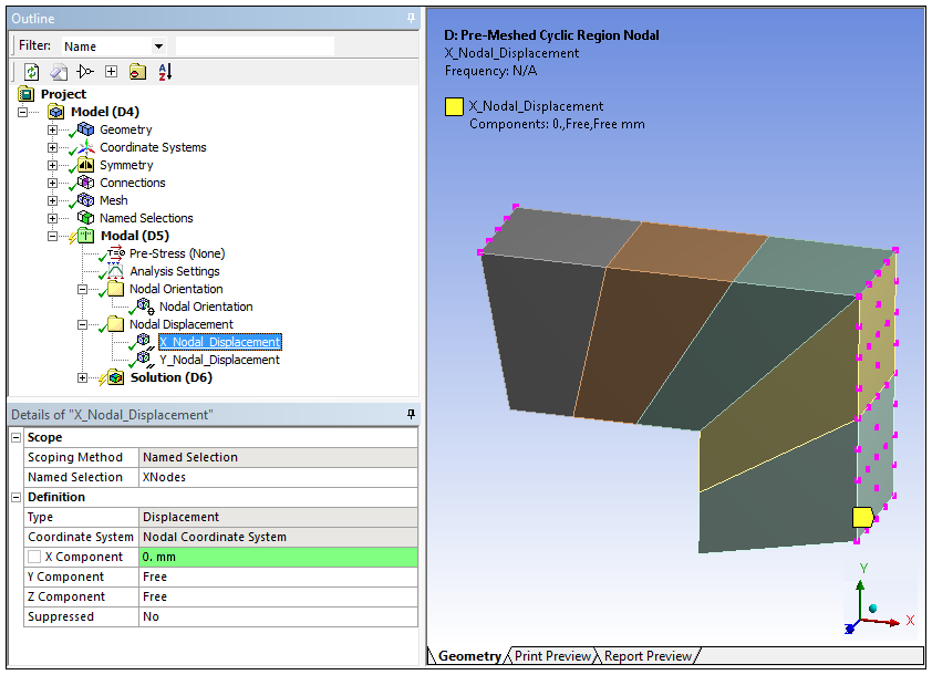
At this point, we have identified three required nodal displacements. However, we find that two of these requirements use the same nodal displacement (X=0). The definitions for the resulting Nodal Displacement objects is illustrated below.
|
X=0
|
Y=0
|
Using the Coordinate System, Named Selections, Nodal Orientations, and Nodal Displacements, we have manually applied the equivalent of a Frictionless Support that is consistent with cyclic symmetry for use in a Pre-Meshed Cyclic Region.