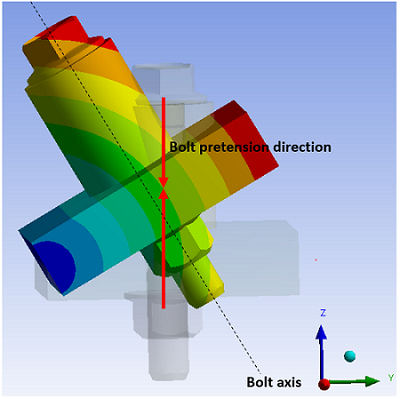
Preloads in bolts and other structural components can often be modeled using the PRETS179 pretension element, as described in Defining Pretension in a Joint Fastener. With this method, the pretension direction remains in the undeformed axial direction of the bolt. If the bolt experiences a large rotation, the bolt preload direction is not updated with respect to the current bolt axis (see figure below). For a large rotation angle, the error in the preload direction may cause significant error in the results.
As an alternative to the pretension element, you can use the MPC184 joint element instead to define a preload section in a joint fastener that undergoes large rotation. The MPC184 element follows the current bolt axis during the large rotation; therefore, errors in the results are negligible. Torque and rotation around the bolt axis may be applied to the joint element.
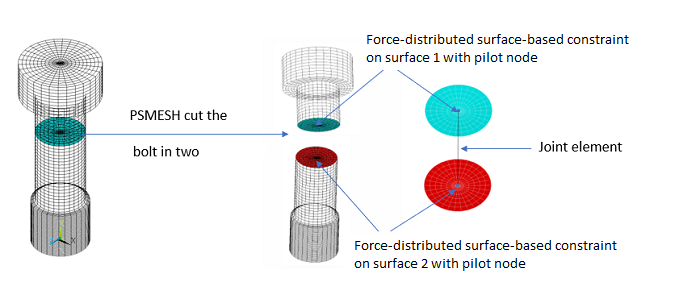
The easiest way to apply a preload section to a fastener is via PSMESH. You can use the command only if the fastener is not meshed as separate pieces.
PSMESH automatically cuts the meshed fastener into two parts and generates the necessary components of the preload section. This typically includes two force-distributed surface-based constraints (remote points) on the cutting surfaces and an MPC184 joint element that connects the two pilot nodes of the force-distributed constraints. (If the joint is between beam elements, no force-distributed constraints are generated.) The command also creates a local Cartesian coordinate system at the first node of the joint element to define the normal direction and saves it as part of the section data.
The elements are created as follows:
Contact Pairs: Two MPC contact pairs (surface-based constraints) are created on the cutting surfaces resulting from the split performed by PSMESH. The program creates CONTA174 (3D) or CONTA172 (2D) elements on each cutting surface along with a pilot node meshed with either a TARGE170 (3D) or a TARGE169 (2D) element at the center point of the contact surface. Appropriate contact and target element type IDs are generated, and a unique real constant ID is assigned to each contact pair. See Table 3.17: Surface-Based Constraints Generated by PSMESH for possible combinations of elements and the contact element KEYOPT settings.
Joint Element: A joint element is created to connect surface 1 to surface 2. The two end-nodes of the joint element are the pilot nodes of the two surface-based constraints.
The type of joint element created depends on the
PSTYPEargument of PSMESH:If
PSTYPEis specified as TORQUE, the program creates a cylindrical joint element (MPC184 with KEYOPT(1) = 11) to represent the preload section as follows:For a 2D model: An x-axis cylindrical joint element is generated along with two force-distributed surface-based constraints. A local Cartesian coordinate system is created at the first node of the joint element such that the local x- axis is the axis of that element (KEYOPT(4) = 0 for the MPC184 element).
For a 3D model: A z-axis cylindrical joint element is generated along with two force-distributed surface-based constraints. A local Cartesian coordinate system is created at the first node of the joint element such that the local z- axis is the axis of that element (KEYOPT(4) = 1 for the MPC184 element).
For a 3D model that contains beam elements: A z-axis cylindrical joint element is generated between the endpoints of two beam elements. (No force-distributed surface-based constraints are needed.) A local Cartesian coordinate system is created at the first node of the joint element such that the local z- axis is the axis of that element (KEYOPT(4) = 1 for the MPC184 element).
If
PSTYPEis specified as a negative value, the program creates a screw joint element (MPC184 with KEYOPT(1) = 17) to represent the preload section. The absolute value ofPSTYPEis used as the pitch value for the screw joint. This option is only valid for 3D models. Two force-distributed surface-based constraints are generated at the cutting surfaces, except for the case of a beam model which does not need the force-distributed constraints. A local Cartesian coordinate system is created at the first node of the joint element such that the local z- axis is the axis of that element.
For all cases, a local Cartesian coordinate system is created to define the joint axis. You can change this local coordinate system via SECJOINT after PSMESH is issued. The new coordinate system you specify must be Cartesian.
Table 3.17: Surface-Based Constraints Generated by PSMESH
| Underlying Elements | Contact Element | Target Element | Contac Element KEYOPT Settings | |||
|---|---|---|---|---|---|---|
| SOLID185, SOLID186, SOLID187, SOLID285 | CONTA174 | TARGE170 |
| |||
| PLANE182, PLANE183 | CONTA172 | TARGE169 |
| |||
| BEAM188, BEAM189 | For beam elements, the joint element nodes are connected to the beam end nodes, and no force-distributed constraints are generated for this case. | |||||
Considerations and Restrictions for Preload Sections
The following considerations and restrictions apply to preload sections that use an MPC184 joint element:
If a preload section is applied on a symmetric geometry model instead of the full geometry model, you must define the symmetry conditions using KEYOPT(6) of the target elements (TARGE169 or TARGE170) for the force-distributed constraints generated by PSMESH. Otherwise, you might get unexpected results. You must also modify the locations of the pilot nodes of the force-distributed constraints so they are at the symmetry plane/edge. For example:
psmesh, , ,1000,all,,0,X,6,,,torque
nmodif,273,6,0,0      ! Pilot node moved to symmetry plane
nmodif,274,6,0,0      ! Pilot node moved to symmetry plane
keyopt,3,6,110        ! Symmetry condition with respect to the xy and xz planes
The displacement adjustment for the MPC184 cylindrical joint element is reported as joint relative displacement and is accessed as an ETABLE quantity. The output item is JRU1 (SMISC,61) for the x-axis cylindrical joint and JRU3 (SMISC,63) for the z-axis cylindrical joint.
All restrictions documented in the Element Reference for the MPC184 cylindrical joint element and MPC184 screw joint element also apply when these elements are used as part of a preload section.
Use of the Lagrange multiplier method (KEYOPT(2) = 3 on the contact element) with the force-distributed constraint is not supported for a preload section.
Joint element preload sections are not supported for shell element models.
Joint element preload sections are not supported in cyclic symmetry analyses.
Joint element preload sections are not supported in linear perturbation analyses.
Use the DJ and FJ commands to apply preloads to the joint element. Load application for the 2D and 3D cases are described below.
Note that if a moment load is not applied to the joint element, the rotational degrees of freedom must be suitably constrained.
2D Case:
A pretension load in the x-direction (FX) can be applied for an x-axis cylindrical joint. ROTX should be constrained as no moment (MX) is applied about the joint axis. The following example shows the typical command sequence.
| Load: Apply an FX force as a proload with the FJ command. Define the force load in the opposite direction of the joint axis to create pretension in the bolt. |
fj,all,fx,-12345.67*2
dj,all,rotx,0
| Adjustment: Apply a displacement as a pre-adjustment with the DJ command. |
dj,all,ux,-.1
| Lock: Fix all displacements using the %_FIX% option of DJ. You may set this state for any load step, except the first one. |
dj,all,ux,%_FIX%
3D Case:
A pretension load in the z-direction (FZ) and a moment about the joint axis (MZ) can be applied to both the z-axis cylindrical joint and the screw joint. ROTZ should be constrained if an MZ moment is not applied. The following example shows the typical command sequence.
| Load: Apply an FZ force as a proload with the FJ command. Define the force load in the opposite direction of the joint axis to create pretension in the bolt. |
fj,all,fz,-12345.67*2
fj,all,mz,10000
or
fj,all,fz,-12345.67*2
dj,all,rotz,0     ! Constrain ROTZ if no moment is applied
| Adjustment: Apply a displacement as a pre-adjustment with the DJ command. |
dj,all,uz,-.1
dj,all,rotz,1.04
| Lock: Fix all displacements using the %_FIX% option of DJ. You may set this state for any load step, except the first one. |
dj,all,uz,%_FIX%
dj,all,rotz,%_FIX%
Use FJDELE to delete the previous load step force before applying the incremental adjustment with DJ.
Use DJDELE to delete the previous load step constraints before applying the incremental load with FJ.
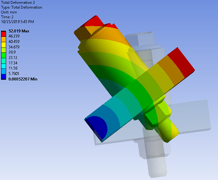
The following example describes the procedure to apply preload to a bolt sleeve model undergoing a large rotation.
Bolt Sleeve Model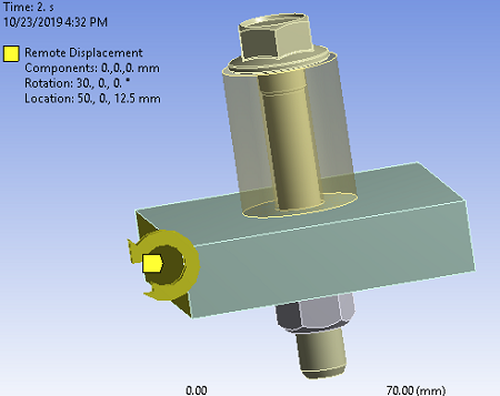 | Initial Meshed Structure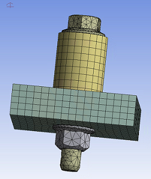 |
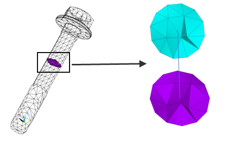
After meshing the bolt sleeve model, PSMESH is used to cut the mesh of the selected bolt elements into two parts and generate the required elements. Two force-distributed surface-based constraints are created (one on each surface), and an MPC184 cylindrical joint element is connected to the two pilot nodes. For this example, a local coordinate system is defined at the cutting location, and the bolt is cut in the z-direction. By default, KEYOPT(4) = 1 is set for the MPC184 element to define the z-axis cylindrical joint.
local,12,0,50.0026090261661,50.0000009547169,40.,-180.,0.,180. nsel,s,,,bolt_node esln psmesh,19,,,all,,12,z,0,,,torque allsel,allIn the first load step, you typically apply a force or a displacement to the joint element with the FJ or DJ command. In this case, the load is applied as a force and a moment in the z-direction. A negative FZ value is used to create the effect of pretension. The force "locks" on the second step, allowing additional loads. The effect of the initial load is preserved as a displacement after it is locked. The full model is rotated around the x-axis 30 degrees to the remote point.
time,1
esel,s,sec,,19
fj,all,fz,-146100.        ! Preload is applied as FZ
esel,all
esel,s,sec,,19
fj,all,mz,170500.         ! Preload is applied as MZ
allsel,all
solve
time,2
esel,s,sec,,19
fjdele,all,all
dj,all,uz,%_fix%          ! FZ is redefined as UZ
dj,all,rotz,%_fix%        ! MZ is redefined as ROTZ
allsel,all
solve
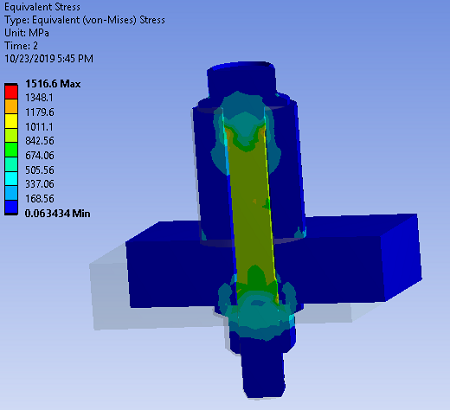
Results
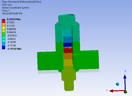
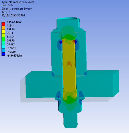
As expected, the axial stress is tensile in the bolt and compressive in the portion of the plates compressed by the bolt heads.
\