


Encoding Geometric Tolerances
Encoded GD&T symbols understand their dimensional and situational context within the model. So, when their attachment references change in space or in type, the symbols update accordingly or become invalid.
GD&T is part of the Product and Manufacturing Information (PMI) exchanged between CAD systems. The PMI Working Group recognizes two levels of information that can be exchanged in the context of explicit 3D geometric shape representation and associated PMI.
- Representation: Describes the exchange of reusable, associative PMI that is not visible in the 3D model. It is used "behind the scenes" by the CAD system and downstream applications.
- Presentation: Describes the exchange of information in a way that is user-visible in the 3D model.
Representation information is pointed to by the definitions shown in the Structure Tree. The geometry that the definitions apply to are recognized as features which are displayed in the tree. Definitions which apply to the features are shown as sub-nodes of the features in the tree. This includes dimensions for features of size. All GD&T items in the Structure Tree are contained in the 'GD&T' folder as shown in the image below.
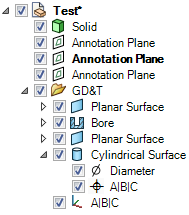
GD&T has its own Structure Tree folder.
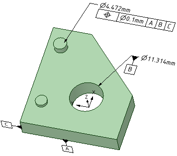
Presentation information is the actual symbol shown in the graphics area and attached to geometry.
Representation stays with the object because it is part of its Structure. Presentation information is built from the representation.
So, when a solid with associated encoded GD&T is moved to a new component:
- Representation information is moved to the new component.
- Presentation information is not moved to the new component. Create new symbols in the component using the Representation information in the Structure Tree.