


Datum Targets
Datum Targets are Points, Lines and axes, or Areas used for establishing a datum. Because of inherent surface irregularities, the entire surface of certain features cannot effectively define a datum. Some examples are:
- Nonplanar or uneven surfaces produced by casting, forging, or molding
- Weldment surfaces
- Surfaces with thin sections subject to bowing, warping, or other distortions
You can think of Datum Targets as representing contact between the part and a measuring gage or fixture. points represent contact with a pointed pin, or a pin with a spherical end. lines represent contact between a cylindrical part and a cylinder on the fixture. Areas represent contact with a flat-ended pin (either rectangular or circular).
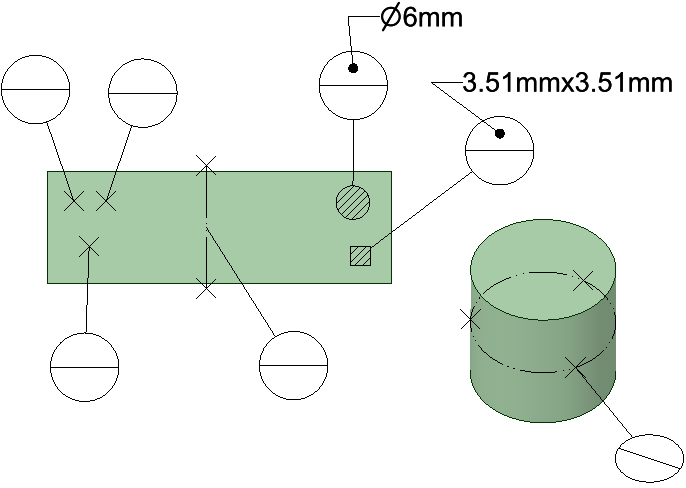
The image below shows the different Datum Targets. From left to right they are, Point, Line, Area (rectangle and Circle), and the three points on the cylinder define a Datum Axis.
Datum targets are all created with a single pick point on a surface. The pick point locates the Datum Target as follows.
- Point - The point
- Area - The centroid of the area
- Line - The midpoint of the line
- Axis - The surface must be cylindrical or conical. The pick point locates a plane defined by three equally spaced points. The axis is perpendicular to the section and passes through the center.
Datum Target Lines are created with a default Length and Orientation. To change either one, select the line and edit its Length or Orientation properties in the Properties Panel.