


Modifiers
When you select a symbol element, the mini-toolbar will present all relevant modifiers.
Their meaning and applicability are described in the relevant sections of ASME Y14.5 (2009) and ASME Y14.41.
Available Modifiers are shown below.
| Symbol | Modifier |

|
At Maximum Material Condition (When applied to a tolerance Value) At Maximum Material Boundary (When applied to a Datum Reference) |

|
At Least Material Condition (When applied to a tolerance Value) At Least Material Boundary (When applied to a Datum Reference) |
|
|
Translation |

|
Projected Tolerance Zone |

|
Free State |

|
Tangent Plane |

|
Unequally Disposed Profile |

|
Statistical Tolerance |

|
Between |

|
All Around |

|
All Over |
Some notes about Modifiers:
- Translation is applied to Datum References (A, B, C, etc.) to indicate the datum can translate within the specified tolerance.
- Projected Tolerance Zone is applied to positional tolerances and includes a minimum projected tolerance zone height. This is typically used to control variation in perpendicularity of threaded or press-fit holes where fasteners could interfere with mating parts.
- Free State is applied to features or datum references that are subject to Free-State Variation. This is the distortion of a part after manufacturing forces are removed. Free State tolerances apply after the removal of manufacturing forces.
- Tangent Plane is applied to tolerances of Form only.
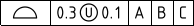
- Unequally Disposed Profile is applied to Profile tolerances to indicate that the
tolerance is not equally applied to the profile. For example, the symbol below
the modifier is between 0.3 and 0.1. This means the total tolerance is 0.3 and
0.1 lies Outside the profile and Adds material. The remaining 0.2
lies Inside the profile and Removes material.
- Statistical Tolerance is used to assign tolerances to related components of an assembly based on sound statistical data.
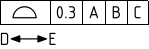
Between indicates that the tolerance applies across multiple features or to a limited segment of a feature between designated extremities.
The example below shows a profile tolerance between D and E. The system prompts you to select a direction and a first and last face to include (first and last can be the same face). It places labels based on the next available letters but you need to create notes pointing to the locations on the faces.
Select the Profile tolerance to modify
Choose Between from the mini-toolbar
Select an edge to set the direction of the limited region or group of features
Select the first face
Select the last face
Complete
- All Around and All Over apply to Profile of Surface symbols attached to dimensions (Attachment Technique = Size Callout)
Diameter and width dimensions for Features of Size can have the Independency modifier added to the Dimension. This revokes Rule #1 in the ASME standard. Rule #1 establishes a boundary of perfect form at the MMC size limit. Rule #1 is also called the Envelope Rule.
To add the Independency modifier, select the dimension, and set the Suspend Envelope Rule property to True in the Properties panel.
An example is shown below.
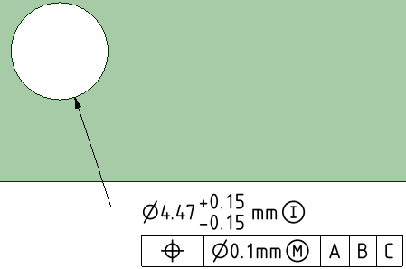
In the ISO standard, the Envelope Rule is not applied by default. So, if you are using the ISO standard and want to apply the Envelope Rule, you need to set the Impose Envelope Rule property to True in the Properties panel.