


Editing the Blocking
Regardless of the blocking technique used, at some point you may need to modify the blocking topology. Typical reasons to do this include:
Subdividing free regions to swept regions or swept regions to mapped regions to get more hex mesh
Making the blocking better conform to the geometry
Simplifying the blocking
Adding boundary layers
Improving feature capture
Improving mesh quality
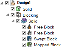
Existing blocks are identified in the structure tree as mapped, swept, or free. You can control blocking display in the graphics window from the Mesh Display panel. Important data about blocks and mesh, either individually or collectively is available in the Properties panel. Also see Understanding the blocking structure.
When editing the blocking topology, it is important to note that the block type affects the choice of operations, and ultimately affects mesh generation. For example, if you split mapped blocks, the split will propagate through faces that have a mapped relationship to the opposite side. For free blocks or swept blocks, a split will terminate at the free face. Similarly, if you set edge parameters on a mapped face edge, opposite edges will necessarily have the same number of nodes. If however, that edge is attached to a free face, the number of nodes on the opposite side will not be adjusted. Understanding this free/mapped relationship will guide you in block editing and help achieve a quality mesh.
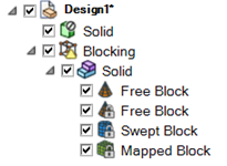
You can lock blocks to preserve the generated mesh topology, so that it cannot be changed during other block editing operations. Locked blocks display a lock icon in the Structure tree, as shown in the image below.
When a block is locked, the mesh sizes on the block will be preserved. The mesh on the locked block(s) will not be recomputed when other blocks are edited, so after editing unlocked blocks the mesh display of the locked blocks will disappear.
Some notes about editing blocks when some blocks are locked:
Blocks that are locked should not be edited. Operations such as merging blocks, reassociating vertices, or converting block type should not be done on locked blocks.
When mapped faces are connected to locked blocks, size changes and topology changes could affect the locked blocks. These changes are managed as follows:
Changes in the number of divisions on a parallel edge that would affect a locked block are not allowed.
Splits of a parallel edge and other operations that can cause split propagation are allowed to maintain connectivity. These changes can modify the locked blocks.
After editing, the Blocking tree state indicates that the full mesh is not up-to-date and must be recomputed as a final step.
Use Generate Mesh to update the mesh to its complete state.
At any point, you may save the blocking topology to a file, independent of the underlying geometry. Typically this is done when you want to use the blocking topology as a template to quickly generate hex mesh on a modified geometry. After opening the blocking file with a new geometry, the software will attempt to associate the blocking topology to the geometry and generate the mesh. Some manual repair and blocking disassociation/reassociation may be necessary.
| To select... | Do this... |
|---|---|
| Block Volumes |
Click a block with the Select block tool guide active. This is available in most block editing tools. Hold the Ctrl key and use the scroll wheel to highlight the volume in the design window. Click the block volume. Click the block name in the Structure tree. Double-click a block vertex. All connected block volumes will be selected. Tip: In the special case of fully mapped blocks, you may select
multiple blocks by first selecting two corner vertices and then using the
RMB context menu . All blocks between the two vertices will be selected.
|
| Block Faces |
Click a block face with the Select face tool guide active. This is available where appropriate in block editing tools. Hold the Ctrl key and use the scroll wheel to highlight the face in the design window. Click the block face. Hold Ctrl to select multiple faces. Double-click block faces for quicker selection of adjacent faces by
flood-filling.
Note: Internal block faces are not supported for
flood-filling. |
| Block Edges |
Click a block edge with the Select edge tool guide active. This is available where appropriate in block editing tools. Hold the Ctrl key and use the scroll wheel to highlight the edge in the design window. Click the edge. Double-click to select a loop of edges. If the selected edge is in more than one loop, repeated double-click will step through the possible loops. Hold Ctrl to select multiple edges. |
| Block Vertices |
Click a vertex with the Select vertex tool guide active. This is available where appropriate in block editing tools. Hold the Ctrl key and use the scroll wheel to highlight the vertex in the design window. Click the block vertex. Hold Ctrl to select multiple vertices. |
| Block Entities |
Select a surface, curve, or point using the Select tool (you may need to disable the Ghost block geometry option). Right-click and select Blocking Entities from the context-menu to select the blocking entities associated with the selection. |
| All blocking volumes, faces, edges and vertices. |
Press Ctrl + A to select all blocking plus bodies as indicated by highlighting in the Structure tree. Use box select to select blocking faces, edges and vertices within the box area. |
| Objects based on search criteria |
|
| Associated geometry | Select the block(s) in the Structure tree or the display
window, right-click and use Select Associated Geometry.
You can also select block faces, block edges, or block vertices in the display
window (when the Ghost block geometry option is enabled),
right-click and use Select Associated Geometry. Note: In case of block entities that are not explicitly
associated to a geometric entity (that is, they are "projected to closest") no
associated geometry is shown. |
| To view... | Do this... |
| Blocks attached to face(s) or block(s). |
Select the block face(s) in the display window with the Select face tool guide active. Select the block(s) in the Structure tree or the display window with the Select block tool guide active. These options are available where appropriate in block editing tools. Right-click and select Show Attached Blocks. |
| Associated geometry | Select the block(s) in the Structure tree or the display window, right-click and select Show Associated Geometry. |
Use the Block Editing tools to perform the following editing actions:
| To ... | Click ... |
|---|---|
| Convert a 3D solid block to 2D surface blocks. | Right-click Blocking in the Structure tree and select Detach Faces. |
| Convert 2D surface blocks to a 3D solid block. Note: The surface blocks
must form a closed, airtight solid. |
Right-click Blocking in the Structure tree and select Solidify. |
| Pull face(s)/edges of a solid block to create new swept/mapped blocks or to cut out swept/mapped blocks from a free block. Pull face(s) of a sheet block to create new solid block(s). |
|
| Select a pair of block faces or edges to split or create a block between the pair of faces/edges. |
|
| Project edges from one side of a free block to another side. |
|
| Divide blocks, block faces or block edges. |
|
| Combine two or more blocks, block faces, or block vertices into a single block, block face, or block vertex, respectively. |
|
| Align block vertices. | |
| Associate block vertices, edges, and faces to geometry vertices, edges, and faces. |
|
| Set the curve shape on a block edge by adding/removing vertices, or by linking/unlinking to other shaped edges. This can improve the mesh quality by helping the mesh conform to the geometry better. |
|
| Check block structures for inconsistencies and fix them, if possible. | Right-click Blocking in the Structure tree and select . |
| Fix inverted blocks. | Right-click Blocking in the Structure tree and select . |
| Validate the blocking. | Right-click Blocking in the Structure tree and select Check Blocking > Validate. |
| Invert the selected blocks. | Select the blocks that you want to invert in the Structure tree, and right-click and select Invert Selected. |
| Move the selected blocks to new material. |
Select the blocks that you want to move to the new material in the Structure tree or the design window, and right-click and select Move to New Material from the context menu. Alternatively, you can select the block(s) in the Structure tree and drag and drop to the material you want to move the block(s) to. |
| Merge block materials. | Select the block materials that you want to merge in the Structure tree,
and right-click and select Merge Materials from the
context menu. Note: You cannot merge block materials across components.
|
| Lock blocks to preserve the generated mesh topology. | Select the block(s) in the Structure tree or the design window, and right-click and select Lock from the context menu. |
| Remove blocks from the topology using the Delete option. | Right-click the block that you want to delete in the Structure tree or select the block in the design window, and then use the RMB context menu or Delete key to remove the blocking. Note that this method does not remove Local settings or controls. |
| Write the blocking topology to a file using the Save option. | Right-click Blocking at the top of the Structure tree. |
| Change the element order (linear or quadratic) for the selected block. | Select the block in the Structure tree and set the Element order in the Properties panel. 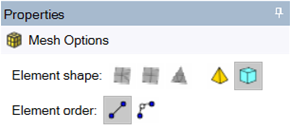 |