


Associating the Blocking to Geometry
The Associate
![]() tool
creates logical links between the blocking topology (faces, edges, vertices) and CAD
geometry (surfaces, curves, points). This allows the blocking, and therefore the mesh, to
be updated automatically when the geometry is modified. It also allows blocking topology to
be reused with similar geometry. When a blocking file is loaded, the software will attempt
to re-associate the blocking topology to the nearest appropriate geometry.
tool
creates logical links between the blocking topology (faces, edges, vertices) and CAD
geometry (surfaces, curves, points). This allows the blocking, and therefore the mesh, to
be updated automatically when the geometry is modified. It also allows blocking topology to
be reused with similar geometry. When a blocking file is loaded, the software will attempt
to re-associate the blocking topology to the nearest appropriate geometry.
Blocking entities may be associated with geometry entities of the same or higher dimension. That is, blocking vertices (0D) may be associated with geometry points (0D), curves (1D), or surfaces (2D); but blocking faces (2D) may be associated only with geometry surfaces. Such associations will constrain independent movement of blocking entities.
Visually, the existence of associations changes the colors of the blocking entities. In this image,
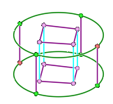
 Red vertices are
associated to geometry vertices. These vertices will be locked to the geometry and will
not move unless you move the underlying geometry.
Red vertices are
associated to geometry vertices. These vertices will be locked to the geometry and will
not move unless you move the underlying geometry. Green vertices
and edges are associated to geometry edge(s). If associated to multiple edges the edges
are treated as a group. If you move a vertex associated to geometry edge(s) the vertex
will move along the associated edge(s).
Green vertices
and edges are associated to geometry edge(s). If associated to multiple edges the edges
are treated as a group. If you move a vertex associated to geometry edge(s) the vertex
will move along the associated edge(s). Purple vertices
and edges are associated to geometry face(s). Edge associations are often related to the
association of the attached faces which can either be associated to a given geometry
face or the closest geometry face (any face). If an edge association looks wrong, you
can often fix the problem by using the Associate tool selecting
the neighboring face(s) and selecting the green checkmark to update the association to
the closest face rather than a specific face. If you move a purple vertex, it will move
along the associated geometry face(s).
Purple vertices
and edges are associated to geometry face(s). Edge associations are often related to the
association of the attached faces which can either be associated to a given geometry
face or the closest geometry face (any face). If an edge association looks wrong, you
can often fix the problem by using the Associate tool selecting
the neighboring face(s) and selecting the green checkmark to update the association to
the closest face rather than a specific face. If you move a purple vertex, it will move
along the associated geometry face(s). Blue vertices and
edges are not associated to the geometry. Blue vertices are moved directly with the move
widget or along the screen position within the Select tool. Blue
edges get their meshed shape in one of the following ways:
Blue vertices and
edges are not associated to the geometry. Blue vertices are moved directly with the move
widget or along the screen position within the Select tool. Blue
edges get their meshed shape in one of the following ways:- Use the Shape/Link tool to control the meshed shape. The mesher can sometimes automatically shape/link edges, you can remove these if needed.
- Edges without any shape/link are either meshed linearly (in case of free blocks) or interpolated if attached to mapped blocks.
When block edges are associated to curves, you can project the edge shape to match the geometry or identify the associated curve.
- To project the edge shape, go to the Mesh Display panel. Under Block display options, enable Projected Shape. The blocking edge will follow any geometry curvature.
- To identify the associated curve, disable Projected Shape and select the blocking edge(s) using the Associate tool. Small arrows will appear between the selected edge(s) and associated curve(s).