Imported Material Field

Imports the initial user-defined field variable values from External Data and map to the mesh. These user-defined Field Variable, are created in the Engineering Data workspace.
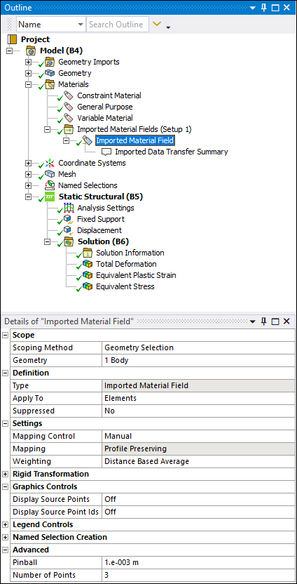
Object Properties

The Details Pane properties for this object include, but are not limited to, the properties listed below. See Appendix B. Data Transfer Mesh Mapping for additional information about other categories and settings for the Imported Material Field object.

CategoryProperties/Options/Descriptions

Scope

Scoping Method

Specify as Geometry Selection (default) or Named Selection.

Geometry

Displayed when the Scoping Method is set to Geometry Selection (default). Displays the type of geometry and the number of geometric entities to which the object has been applied using the selection tools. Use the selection filter to pick geometry, click in the Geometry field, then click Apply.

Named Selection

Displays when the Scoping Method is set to Named Selection. This field provides a drop-down list of available user-defined Named Selections.

Definition

Type

A read-only property that describes the object: Imported Material Field.

Apply To

Options include Elements (default) and Corner Nodes. This property specifies whether the external values are mapped to all the nodes of the elements of the mesh or to the corner nodes only.

Suppressed

Suppress the object as desired.

Graphics Controls

Display Material Field

When you have more than one material field variable specified in the worksheet, this option enables you to select the variable you wish to display.

Display Source Points

Toggle display of source point data. Options include Off (default) and On.

Display Source Point Ids

Toggle display of source point data identifiers. Options include Off (default) and On.

Display Interior Source Point

Toggle display of internal source point data. Options include Off (default) and On.

Settings

Mapping Control

Options include Program Controlled (default) and Manual.

Mapping

A read-only property that describes the setting: Profile Preserving.

Weighting

Select the type of weighting to be performed. This option can be changed only if the Mapping Control property is set to Manual. The default setting is Triangulation.

Transfer Type

A read-only property that describes the setting: Volumetric.

Rigid Transformation

Mesh Alignment

Provides a drop-down menu that includes the options Use Origin and Euler Angles and Use Coordinate Systems.

Origin XYZ and Theta XY/YZ/ZX

These properties display when the Mesh Alignment property is set to Use Origin and Euler Angles. You use these properties to change the source point coordinate locations.

Source/Target Coordinate System

These properties display when the Mesh Alignment is set to Use Coordinate System.

Legend Controls

Legend Range

Options include Program Controlled (default) and Manual.

Minimum

Displays when the Legend Range property is set to Manual. The default setting is Program Controlled. Select the field to make a manual entry.

Maximum

Displays when the Legend Range property is set to Manual. The default setting is Program Controlled. Select the field to make a manual entry.

Minimum Source

A read-only property that describes the setting: Program Controlled.

Maximum Source

A read-only property that describes the setting: Program Controlled.

Named Selection Creation

The following properties enable you to create Named Selections for Mapped, Unmapped, and Outside elements identified during the mapping process.

Unmapped Nodes

Options include Off (default) and On. Selecting the On option displays the Name property. Rename the default as desired.

Mapped Nodes

Options include Off (default) and On. Selecting the On option displays the Name property. Rename the default as desired.

Outside Nodes

Options include Off (default) and On. Selecting the On option displays the Name property. Rename the default as desired.

Tree Dependencies

  • Valid Parent Tree Object: Imported Material Fields group.

  • Valid Child Tree Objects: Comment, Figure, and Image objects.

Insertion Methods

This object appears automatically as a child object of the Imported Material Field group when you have a properly specified Material Field Data in an External Data system linked to the Mechanical Model cell on the Workbench Project page.

To add additional Imported Material Field objects after highlighting the Imported Material Fields group object:

  • Select the Imported Material Field option on the Imported Material Fields Context tab.

  • Right-click theImported Material Fields folder and then select Insert > Material Field.

  • Select the Imported Material Fields folder and then in the Geometry window, select geometry, then right-click and select Insert > Material Field.

Right-click Options

In addition to common right-click options, relevant right-click options for this object include:

API Reference

See the Imported Material Field section of the ACT API Reference Guide for specific scripting information.

Additional Related Information

See the following sections for more information: