


Material data can be dependent on variables such as temperature, shear angle, degradation factor, or user-defined entries. These variables known as field variables and are only available for specific material properties and models, as listed below. For more information on this topic, see User-Defined Field Variables in the Material Reference.
Engineering Data supports the following field variables:
Coordinate X
Coordinate Y
Coordinate Z
User-defined variables (as discussed below).
The use of field variables to further define material properties enables you to simulate the effects of environmental conditions and manufacturing processes on material characteristics. This can be of particular importance when you are using the Ansys Composite PrepPost application to model composites. See Variable Material Data in Composite Analyses in the ACP User's Guide for additional information.
The material properties and models supported by the field variable feature are based on the selected analysis system. See the Supported Properties section of the documentation for a listing of all of the supported analysis types and the material properties that each analysis supports. Note that certain properties are appended with a function notation to indicate supported fields. This includes:
Temperature (T)
Frequency (F)
Coordinate X (C)
Coordinate Y (C)
Coordinate Z (C)
User-defined (U).
Note: The coordinate system assigned to the body in the analysis is the coordinate system used for the field variables Coordinate X, Y, and Z. Only Cartesian coordinate systems are supported.
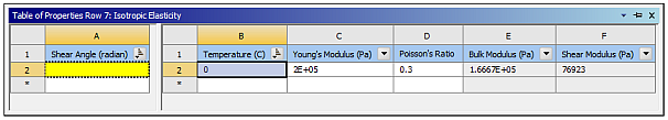
The Shear Angle and Degradation Factor field variables are predefined user-defined variables. Based on this, isotropic elasticity supports all field variables and is denoted as: Isotropic Elasticity f(T,F,U).
However, for Modal Acoustic analysis system, only temperature is supported and so denoted as: Density f(T). For material properties that are defined with unsupported field variables, the application uses the default value for the unsupported field variables to calculate dependent values for the supported field variable(s) values. For example, during a Modal Acoustics analysis, you can enter frequency dependent and/or temperature dependent material properties, however:
If you define frequency dependent material property data, f(F), your input is calculated using the interpolation of the General Interpolation Library (GIL) based on the default frequency value of the Material Field Variables property.
If you define frequency-dependent and temperature-dependent material property data, solver input is calculated using both the GIL, based on default frequency, and the defined temperature points, for example, f(Fdefault, T). Any change to the default frequency value may vary the interpolated values.
Defining System Provided Field Variables
To implement a system provided field variable:
Select one of the supported material properties (as listed above).
The application displays the Field Variables category in the Toolbox.
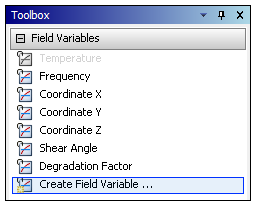
From the Field Variables category, select the desired system provided field variable:
Temperature
Frequency
Coordinate X
Coordinate Y
Coordinate Z
Shear Angle
Degradation Factor
The new field variable populates the Table pane. Enter appropriate values.
Enter appropriate values into the Table pane.
Creating User-Defined Field Variables
To implement a user-defined field variable:
In the Toolbox, select from the Field Variables category.
In the Create Field Variable dialog box, enter a name for your new field variable.
Select an option from the Quantity Type drop-down list.
The default is .
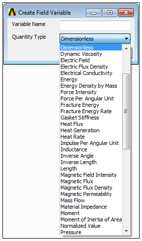
Once complete, click .
The new field variable populates the Table pane.
Enter appropriate values. Example entries are illustrated below for the user-defined field variable
Example_Custom_Fld_Var.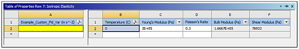
Select the Interpolation Options property to display the following Table pane.
This table defines the algorithm the solver uses to interpolate between the data entered in the Table pane from Step 2 to get the values corresponding to the calculated field variable values on a given element. See General Interpolation Library in the ACP User's Guide for more details about the algorithms and options used when creating user-defined field variables.
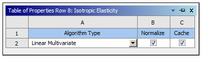
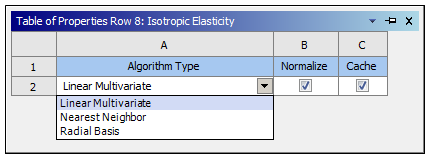
Select an option from the Algorithm Types drop-down list.
Refine the interpolation algorithm by activating one or more of the following options.
Normalize: Scale the axes to achieve an unbiased distance metric. The ranges used to scale the axes are defined by the Lower Limit and Upper Limit values of the Material Field Variables table pane.
Cache: Save previous queries to increase performance.
Select the Material Field Variables property to display the following table pane.
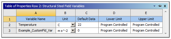
Field descriptions for the Material Field Variables property:
Default Data: Used by the interpolation algorithm when the corresponding field variable is not defined on a given element.
Lower Limit: Defines the lower boundary on the range used when the data is normalized and/or quantized. When you use the setting, the value defaults to the minimum value of the data entered for all instances of the corresponding field variable in the selected material.
Upper Limit: Defines the upper boundary on the range used when the data is normalized and/or quantized. When you use the setting, the value defaults to the maximum value of the data entered for all instances of the corresponding field variable in the selected material.
Usage Notes
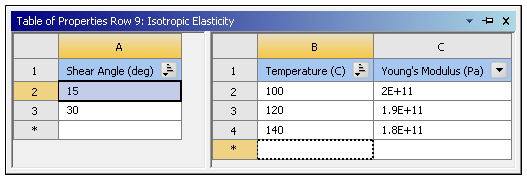
The order in which you add field variables to a material property becomes important if:
Your material data has multiple field variables.
The data is structured such that one field variable changes while the others remain fixed.
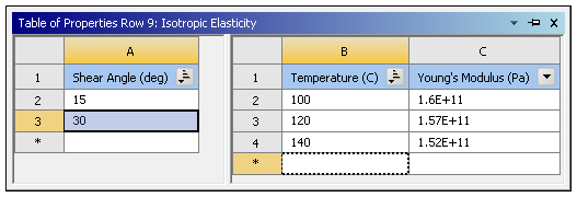
Whichever field variable varies the most, is the variable that you should insert and define first. Consider the example illustrated below. In this case, the Temperature varies more than the Shear Angle, so it is best to add temperature first and then shear angle. Adding the field variables in this order results in a table structure that, for each shear angle, there is data at multiple temperatures.
The context menu on the Table pane for the field variable provides sorting and filtering options.
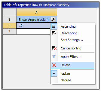
To remove a field variable from a property, right-click the field variable and select from the context menu.