


Specify a domain in which the mesh is adapted, or "morphed," based on node locations and coordinates, during the solution process to adapt the mesh to the current frequency. The analysis supports only one Morphing Region object. Once inserted, the option is no longer available on the ribbon/context menus.
 |
Object Properties
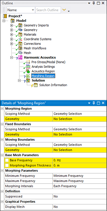
The Details Pane for this object includes the following properties.
| Category | Properties/Options/Descriptions |
|---|---|
|
Morphing Region |
Scoping Method: Specify how you perform geometric entity selection. Options include (default) and . Geometry (Body selection only): Visible when you set the Scoping Method property to . Select a body or bodies to specify the domain for mesh that will be adapted during the solution. Once you make selections, the property displays the corresponding number of scoped geometric entities (1 Body, 2 Bodies). Named Selection (Body selection only): Visible when the Scoping Method is set to . Provides a drop-down list of user-defined Named Selections that meet the scoping requirements for the object. |
|
Fixed Boundaries |
Scoping Method: Specify as (default) or . Geometry (Face selection only): Select the face or faces corresponding to the face/faces for which the mesh does not change during the solution process. Named Selection: Visible when the Scoping Method is set to . Provides a drop-down list of available user-defined face-based Named Selections. |
|
Moving Boundaries |
Scoping Method: Specify as (default) or . Geometry (Face selection only): Select the face or faces that define the boundary of the of the mesh that is automatically adapted during the solution process. Mesh adaptation is based on the values of the Base Frequency and Morphing Region Thickness properties. Named Selection: Visible when the Scoping Method is set to . Provides a drop-down list of available user-defined face-based Named Selections. |
|
Base Mesh Parameters |
Base Frequency: Specify the frequency of the base mesh (displayed mesh). The solver uses the Mechanical Mesh at this frequency but modifies it using additional/other frequencies during the solution. This frequency is the frequency used for the acoustics requirements. You can set this property as a parameter. Morphing Region Thickness: Specify the average thickness of the bodies scoped to the Morphing Region. You can set this property as a parameter. |
|
Morphing Parameters |
Minimum Frequency: This value defaults to the setting of the Range Minimum property specified in the Options category of the Analysis Settings object. For this default setting, the property displays the entry Minimum Frequency. You can change this value and the solver will use the value to update the mesh when solving at a lower frequency. Maximum Frequency: This value defaults to the setting of the Range Maximum property specified in the Options category of the Analysis Settings object. For this default setting, the property displays the entry Maximum Frequency. You can change this value and the solver will use the value to update the mesh when solving at a higher frequency. Morphing Intervals: The default setting of this property is Each Frequency. You can enter a value for this property and the solver updates the mesh for every n number of substeps. |
|
Sliding Constraints (Beta) |
Sliding Constraints (Beta): When the Show Beta Options (Options > Common Settings > User Interface) preference is active, this property enables you to force the nodes of the selected planar faces to stay in the plane during morphing to properly represent the presence of symmetry or ground. |
|
Definition |
Suppressed: Include or exclude the object from the analysis. Options include (default) and . |
|
Graphics Display |
Display Mesh: Display the adapted or "morphed" mesh of the Morphing Region for a specified Morphing Frequency. Options include and (default). When you select , the Morphing Frequency property displays. The mesh displayed corresponds to the adapted mesh at this frequency. Morphing Frequency: Specify the desired frequency at which to display the adapted mesh. |
Tree Dependencies
Valid Parent Tree Objects: Environment.
Valid Child Tree Object: This object does not support child objects.
Insertion Methods
Use one of the following methods after highlighting Environment object:
Select the Morphing Region option from the Physics group of the Environment Context tab.
Right-click and select > .
Right-click in the Geometry window and select > .
Right-click Options
In addition to the common right-click options, the object includes the following right-click menu options:
Acoustics > [Supported Acoustics Boundary Conditions].
API Reference
See the Morphing Region section of the ACT API Reference Guide for specific scripting information.
Additional Related Information
See the Harmonic Acoustics Analysis section for more information.