


Imports external mesh file. Once imported, the application updates the Geometry object with the imported parts/bodies as well as any additional finite element data. See the Importing Mesh-Based Geometry for more information about imported data types.
Object Properties
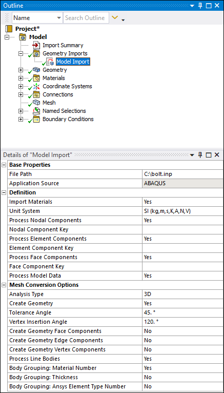
The Details Pane for this object includes the following properties.
| Category | Properties/Options/Descriptions |
|---|---|
|
Base Properties |
File Path: Directory location of the imported file. Application Source: The name of the application used to create the imported file. Supported types include MAPDL, ABAQUS, and LS-DYNA. |
|
Definition |
Import Materials: Automatically import materials from the source file. Options include (default) and . Unit System: Specify the desired unit system in which the file is defined. Source points are interpreted in these units. Process Nodal Components: The application automatically imports node-based components defined in the mesh files as node-based Named Selections. Options include and (default). Nodal Component Key: This entry field enables you to filter and import only those node-based components that start with a specified name/string value in the mesh files. For example, you want to import only node-based components that start with the prefix string "nodal_*." Enter that string into this field and the application filters through all component names and returns only the components that begin with this key string value. Process Element Components: The application automatically imports element-based components defined in the mesh files as element-based Named Selections. Options include and (default). Element Component Key: This entry field enables you to filter and import only those element-based components that start with a specified name/string value in the mesh files. For example, you want to import only element-based components that start with the prefix string "elemental_*." Enter that string into this field and the application filters through all component names and returns only the components that begin with this string value. Process Face Components: The application automatically imports face components defined in the mesh file as face-based Named Selections. Options include and (default). Face Component Key: This entry field enables you to filter and import only those face components that start with a specified name/string value in the mesh files. For example, you want to import only face components that start with the prefix string "face_*." Enter that string into this field and the application filters through all component names and returns only the components that begin with this string value. Process Model Data: The application automatically processes all external file data. Options include and (default). When set to , the application only processes data directly needed for the creation of the mesh and geometry of the external file and ignores any other data, such as Connections and engineering abstractions such as plies, bolt pretensions, boundary conditions, etc. Process Mesh200 Elements: This option supports Mechanical APDL common database .cdb files only. Options include (default) and . When selected, Mesh200 elements present in your mesh file are included with your geometry in Mechanical. Check Valid Blocked CBD File: This property displays when the Application Source property is set to (default). This property instructs the application to verify that the specified file is a valid Blocked .cdb file, Options include and (default). The application only supports Blocked format. If the property is checked and the file is not a valid blocked file, an error message displays. As needed, you can import your model into the Mechanical APDL application and properly archive the model. Use the PREP7 command CDWRITE,DB to create a compatible file. Important: If you set this property to and your file is not a valid Blocked .cdb file, the application may not properly import your model. |
|
Mesh Conversion Options |
Analysis Type: Defines the mesh file as (default) or . When you set this property to the option, the application validates that the geometry is two-dimensional (2D) by checking the value of the Length Z property, using CAD units, in the Bounding Box category of the Geometry object. The tolerance used for this check is based on the setting of the 2D Tolerance property (Properties category of the Geometry object). If you change the value of the 2D Tolerance property, you must refresh the analysis in order for the application to re-validate the geometry. Create Geometry: The application automatically creates your geometry based on solids, shells, and beam elements (that have an assigned cross-sectional definition) present in the mesh. Options include and (default). Setting this property to instructs the application to import the mesh only (elements and nodes). When imported, the application creates Element Groups object in pl,ace of the Geometry object. The Element Groups object and its children behave as a Geometry object and its children. That is, the Solid, Surface, and Line elements behave as bodies. Not creating a geometry dramatically decreases your import time as well as significantly reducing the amount of memory used during the process. Tolerance Angle: This value determines if adjacent elements
are of the same face during the geometry creation process. The default value and
recommended setting is Vertex Insertion Angle: This angle is the minimum angle to
insert a vertex between two free edges of mesh. The default value is
Create Geometry Face/Edge/Vertex Components: These options become active when your mesh file contains node-based named selections. Options include (default) and . When set to , the application automatically creates geometric named selections (face/edge/vertex). For a vertex or an edge, the node-based named selection can include only include one node or one edge. For faces, nodes from multiple faces can be included in the node-based named selection. This option will not affect the geometry creation algorithm itself, which is based purely on the mesh adjacency angles as detailed above. Note: The application automatically transfers geometry-based Named Selections for faces. Process Line Bodies: This property enables you to import finite element line bodies (see Line Bodies) that have a properly defined cross-section. For these finite element line bodies, the following element types are supported.
Body Grouping Material Number: [a]Group elements based on the material number assigned to the elements. The application creates a group for each Material Number. Options include and (default). Body Grouping Thickness: [a] Group all elements that have the same thickness number. Options include (default) and . Body Grouping Ansys Element Type Number: [a] Options include (default) and . For Mechanical APDL common database (.cdb) files only, this option enables you to group elements by their local Ansys element type that was assigned from the element library. Note that the element type number is the first argument to the ET command in the (.cdb) file. Important: For LS-DYNA files, Mechanical creates only one part. Elements are grouped into bodies first by element shape then by Part ID as defined in the LS-DYNA file and then (if chosen), by Material Number or Thickness. Therefore each element in a body will have same shape, LS-DYNA Part ID and (if chosen), and same Material Number and Thickness. In addition, each body listed in the Outline has its part name specified using the *PART keyword in the input file. |
[a] These properties tell the application how to group the elements (of the same type) from the data file. The application always groups by shape and places different shaped elements in separate groups. The options control the number of element groups/bodies created. You use these properties to specify how you want to group elements. You can set one or more of these properties to .
Tree Dependencies
Valid Parent Tree Objects: Geometry Imports.
Insertion Methods
The application automatically inserts this object once you have selected a desired external mesh file using the Add Model Import option.
Right-click Options
In addition to certain common right-click options, this object includes the option , used to imported the mesh data for the file you select.
Additional Information
See the Import External Model (Mesh) File topic in the Importing Geometries or Mesh from Mechanical section of the Mechanical User's Guide.