Examples of a geometry that results from a synthesis for a given mesh with different Tolerance Angle settings and Component Key specifications are illustrated below.
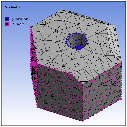
Meshed Model
This illustration is a graphical representation from Mechanical of the node data provided by a .cdb file. Two nodal components have been processed: CylinderNodes and SideNodes.
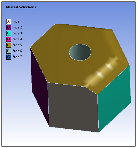
45° Tolerance Angle
This illustration represents a synthesized geometry that includes faces created using a 45° Tolerance Angle.
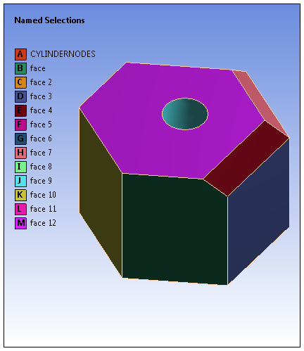
25° Tolerance Angle
In this illustration, the Tolerance Angle was specified as 25°. This resulted in an accurate synthesis of the geometry.
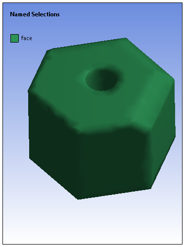
180° Tolerance Angle
This example illustrates how only one face is generated for the geometry when no tolerance angle (180°) is specified and no node-based components are processed. This type of result can also occur when a node-based component contains all of the nodes for a given body.