


The steps to import geometry or external model (mesh) files depend upon how you have opened the application.
Go to a section topic:
Mechanical Opened Independently
Mechanical Opened from Workbench
Material Assignment By default, when you first import your model into Mechanical, any bodies that do not include material assignment are assigned the application's default material. If you subsequently update your geometry from the source application, Mechanical does not assign default materials to new bodies. If the geometry update includes a new body without an assigned material, the body becomes underdefined and requires you to specify a material.
Mechanical Opened Independently
When you open Mechanical independently, you can import either geometry or an (external) model file.
- Import Geometry
Select the object.
Select the option from the Context tab. The Add Geometry Import option includes a drop-down menu that lists recently imported files as well as the option that opens a dialog to select a file.
From the dialog, select a desired geometry file from the dialog.
The Import Geometry dialog displays automatically. This dialog includes two tabs: Basic and Advanced. Change property settings as needed and select the Import button.
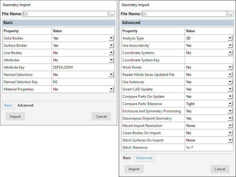
Important: The global / behavior is defined by the Analysis Type property of the Advanced property pane and is determined when you first import geometry for your session. In order to change it once specified, you need to reset the project using the > option and reimport your geometry.
The application automatically imports the selected geometry and adds a Geometry Import object to the Outline. The application also updates the Geometry object with the imported parts/bodies.
- Import External Model (Mesh) File
Select the Geometry Imports object.
Select the Add Model Import option from the Geometry Imports Context tab.
Select a desired Mechanical APDL (MAPDL) common database (.cdb) file, LS-DYNA Input (.k and .key), or Abaqus (.inp) file from the dialog that displays. The application automatically inserts a Model Import object into the Outline and displays an associated context tab.
Specify Details pane properties of the Model Import object as needed and then select the Import option from the context tab or the context (right-click) menu.
Once imported, the application updates the Geometry object with the imported parts/bodies as well as any additional finite element data, such as connections, boundary conditions, and Named Selections. See the Importing Mesh-Based Geometry for more information about imported data types.
Mechanical Opened from Workbench
When you open Mechanical without a geometry, use the Geometry Imports folder and the child Geometry Import object to import geometries into Mechanical.
- Import Primary Source
The “primary source” is the geometry imported from Workbench. For convenience, it can now be attached directly from Mechanical. The primary source uses the current Basic/Advanced Geometry Preference settings for the Geometry cell in Workbench.
Note: If you have already imported geometry, a secondary source geometry is added instead. See the description below.
Select the Geometry Imports folder, and, using the Context tab Geometry Imports, either:
Click the Import Geometry option. A file selection dialog displays that enables you to select the desired file.
Or...
Expand the drop-down list for the option to select a model from the list of recently imported geometries. For convenience, a option is also available.
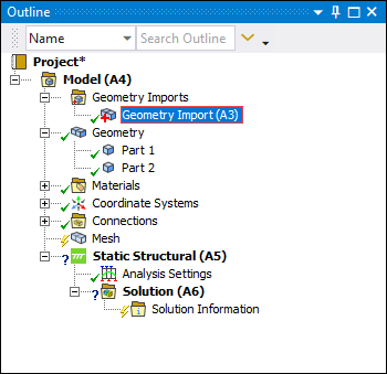
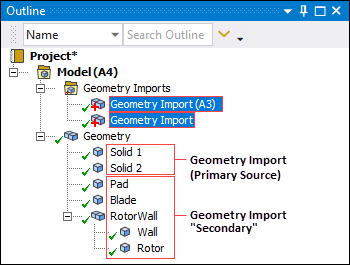
If no other geometries are currently imported, the application automatically imports the selected geometry and updates the Geometry Import (A3) object. The application adds parts/bodies (for example, Part 1 and Part 2 shown below) as children to the Geometry object.
- Import Secondary Sources
Non-primary sources are referred to as "secondary" geometries/models. These are imported into Mechanical separately. Separate preferences can be specified for each import.
Once you have a model imported into Mechanical, you can add additional models using the Geometry Imports features. Use the steps below to add models to your analysis.
Select the Geometry Imports object, and using the Context tab Add Geometry Import option, either:
Select the option. A dialog displays that enables you to navigate to the desired file.
Or...
Expand the drop-down list for the option to select a model from the list of recently imported geometries. For convenience, a option is also available.
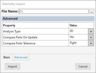
As illustrated below, change the Basic and/or Advanced properties of the Geometry Import property pane. This property pane displays automatically.
Note:Parameters are not supported for secondary imports.
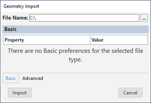
As illustrated, for DesignModeler and SpaceClaim files, the pane includes fewer properties.
In general, these are the same preferences that are available for the Geometry cell of an analysis system on the Workbench Project Schematic before you have specified a model to import. You should review the Geometry Preferences section of the CAD Integration documentation as well as the Geometry Import section of the Workbench User's Guide for additional information.
Select Import. A secondary Geometry Import object is automatically inserted into the outline, as illustrated below. The parts/bodies (shown below as Pad, Blade, and Rotor) are added as children to the Geometry object.
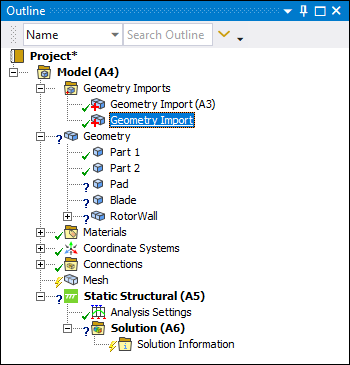
Important: The application does not automatically assign materials to secondary imports. Note the "?" state for the above parts under the Geometry object. You need to manually specify a Material for the parts.
In the example below, you can see an example with parts and bodies under the Geometry object from multiple Geometry Import objects. Note that there is no separation or special treatment between parts/bodies from either Primary or Secondary sources.
Tip: For convenience, you can display the context (right-click) menu on the Geometry Import objects and select the option > , to automatically select the parts/bodies for the import object. For CAD models, you can replace the geometry as desired using the Replace Geometry option on the Geometry Context tab.
Limitation: Working with Model Assembly and Secondary Geometries
If you have an analysis that includes model assembly, be sure to perform this operation before importing any secondary geometries. Existing secondary geometries are lost during the model assembly process.
Tip: For Windows systems only, you can drag and drop a supported geometry or mesh file directly into the Geometry window. The application automatically attaches the model to the analysis system. For mesh files opened from Workbench, the application automatically inserts an upstream External Model system linked to your analysis system. Imported mesh files adopt the default unit system.
For CAD models, you can replace the primary and secondary source geometries using the options.