


A surface is categorized as a form of construction geometry and is represented as a section plane to which you can scope surface results or reaction probes.
To define a surface:
Highlight the Model object, open the drop-down menu on the Model Context Tab, and select .
Define a coordinate system whose X-Y plane will be used as a cutting plane, as follows:
Define the origin of the local coordinate system.
Note: With respect to the facets of the surface:
For a Cartesian coordinate system, the surface is the intersection of the model with the X-Y plane of the coordinate system.
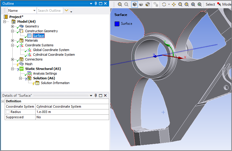
For a cylindrical coordinate system, the surface is the intersection of the model with the cylinder whose axis is the Z axis of the coordinate system. In this case, you must specify the radius in the Details view of the Surface object.
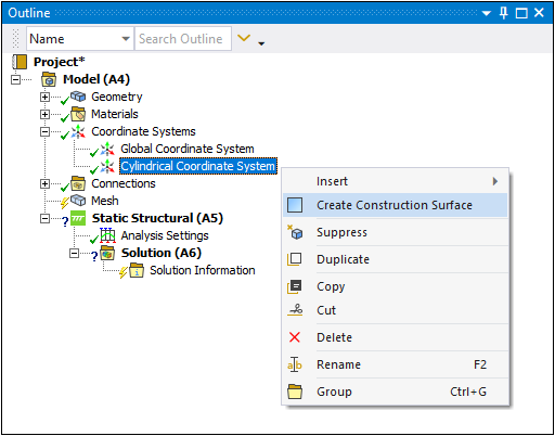
Tip: For an existing coordinate system, you can define a Surface Construction Geometry object by selecting a desired Coordinate System object, right-clicking, and selecting . This feature allows you to define the coordinate system first. See the procedure below.
Create Construction Geometry Surface from Coordinate System
As illustrated below, you can create a Surface Construction Geometry from any existing coordinate system using the right-click feature .
| Right-click Menu for |
|
|
| Details for Surface Object |
|
The Details display the defined coordinate system, Radius, and enables you to suppress the object if desired.
|