


The first node on the Simulate User Interface Workflow tree is Geometry. This provides options for loading predefined mesh or geometry files, generating sector meshes and creating criteria for automatic generation of meshes during the simulation. Items under the Geometry node represent the surfaces bounding the system of interest. When an item under the Geometry node is selected, the Editor panel below the Workflow tree displays information about the limiting coordinate values represented by that surface. The icon bar in the Editor panel for a selected surface provides action icons that can be applied to the surface, including Rename, Split Mesh, Transform Mesh, and Invert Normals. You can also right-click a selected item in the Geometry tree to access the associated commands from a context-sensitive menu. Transforming a mesh is accomplished in a reference frame and allows scaling, translation, rotation, and leaving a copy at the current coordinates. Splitting a mesh has options to use a Feature Angle or to Cut by Plane (with a reference frame). For Feature Angle, the default value of 25 Min. Face Count for Split Regions means each region will have a minimum of 25 triangular mesh faces.
The icon bar for the Geometry node itself provides icons relating to mesh creation, including Launch Sector Mesh Generator, Import Geometry, Export Geometry, and Merge Meshes, Join Meshes, and Measure Geometry. These actions are described in the sub-sections below.
For more details on the following items in the Geometry tree, read these sections in Overview of Ansys Forte Simulation:
Note: The Invert Normals command for surfaces is supported by the View Normals command, which makes the Normals visible. View Normals is available as a right-click command in the Visibility tree (which can be displayed on the right side of the Simulate panel, using the command). The displayed normals look like needles projecting from the exterior face of the surfaces. If a surface does not have the needles pointing in the desired direction from the exterior face, use the Invert Normals command. (The Forte Quick Start Guide provides an example of inverting Normals.
Using the Automatic Mesh Generator has two additional requirements:
Note: These two conditions are not required for body-fitted mesh cases.
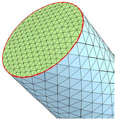
The mesh must be watertight so that the automated meshing does not escape the confines of the specified surface. If a mesh has a leak (is not watertight), then a series of red lines will appear at the edges of a surface in the 3D View, indicating the problem area. There are typically 3 reasons for this situation:
The edges do not match, as shown in Figure 3.1: Nonwatertight surfaces that cause this mesh to leak, because the edges do not align.
The mesh has duplicated surfaces, leaving some surface edges unmatched to neighbor surfaces.
The mesh has poor resolution and requires a relaxed tolerance to generate a watertight mesh.
For a surface to be considered watertight, the following conditions must be met:
When joining edges within a mesh, the default tolerance is 0.000001 cm. You can modify this with the Merge Meshes Utility, as described in Join Meshes Utility.
The Top Dead Center location of the piston is required for automatic meshing to prevent reversing the directions of the normals for the wall faces in the compression stroke. The TDC position also reduces the number of triangle faces in the initial mesh.
Engine projects that were created in versions of Ansys Forte that predate
this requirement will automatically be updated at the time of project launch. The updater cuts
the wall surface at the stroke height, shifts the moving surface all the way to top dead center,
and joins the moving surface to the wall. If there is any irregular surface, the automated mesh
update attempts to stitch it together but will abort if the original mesh is not watertight. The
same functionality is available in the BDC-TDC Transform utility in the
Utility menu and as an icon  on the toolbar.
To check for correct normal vector orientation, use the ![]() button located on the Geometry Editor panel or the ribbon. This will check
for normal vector consistency. Potential problems will be described in the log window. Surface
normal vector orientation may be corrected by clicking the Invert Normals
option on the individual surface patches.
button located on the Geometry Editor panel or the ribbon. This will check
for normal vector consistency. Potential problems will be described in the log window. Surface
normal vector orientation may be corrected by clicking the Invert Normals
option on the individual surface patches.