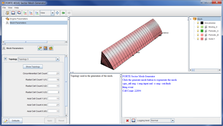
The Sector Mesh Generator  icon launches the Sector Mesh Generator window, which has a workflow and
layout similar to Ansys Forte Simulate. Sector meshes are used to represent in-cylinder combustion
where there is symmetry that is periodic around, for example, the nozzle holes associated with
the fuel-spray injection in a diesel engine. A symmetric 8-hole layout, for example, may be well
represented with a 45-degree sector mesh. The Sector Mesh Generator will generate a
Forte-compatible, body-fitted sector mesh using a minimal number of user specifications that
define the engine piston motion and bowl shape. The Workflow tree of the Sector Mesh Generator
has nodes for Engine Parameters and Mesh Parameters, while the 3-D View window is used to
preview the mesh and mesh-control settings.
The Engine Parameters panel allows specification of the piston bowl profile, piston-motion characteristics, sector angle or sector cyclic symmetry, as well as engine-cylinder dimensions, and crevice dimensions.
Note: The crevice model cannot be used (see Crevice Model) if the crevice block is included in the mesh.
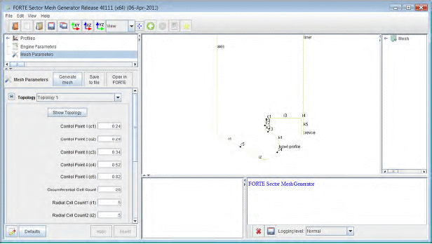
The Mesh Parameters panel allows control of the mesh density and topology as shown in Figure 3.2: Sector Mesh Generator interface. Using the Sector Mesh Generator is described in Sector Mesh Generator.
For in-cylinder-only simulations, Ansys Forte includes a built-in mesh
generator with five possible topology configurations. The Sector Mesh Generator requires
specification of basic engine parameters as well as some control parameters for each mesh
topology. From this basic information, the Sector Mesh Generator automatically generates and
loads a sector mesh with the selected topology. To use the mesh generator, select the Generate
Mesh tab and specify the required parameters in the panel. When the parameters have been
specified and applied, click the Generate Mesh  icon to generate and import the mesh.
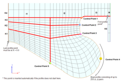
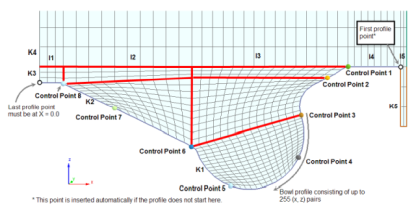
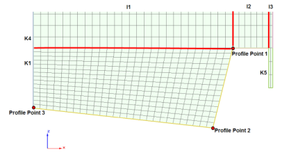
The Sector Mesh Generator (SMG) constructs one of five mesh topologies as shown in Figure 3.3: Example topology 1: Mesh built by automated Sector Mesh Generator to Figure 3.7: Example topology 5: Mesh built by automated Sector Mesh Generator below. The input in the Editor panel controls how the topology is mapped onto the actual engine-cylinder geometry (see Figure 3.8: Interface for automated Sector Mesh Generator ). For the mesh the Z axis is always assumed to be in the vertical direction, along the axis of the engine cylinder, pointing upward toward the cylinder head. The (X,Y,Z) origin is assumed to align with the center of the cylinder, at the vertical height corresponding to the top of the piston bowl.
Most of the topologies require control point locations along the bowl profile to aid in mapping the topology to the actual geometry. The control point locations are entered as fractional lengths along the bowl profile, that is, a control point fraction value of 0.1 would indicate the control point should be placed 10% of the distance along the bowl profile curve, starting from the edge of the bowl profile near the cylinder wall.
Parameters Cell Count K1, K2, K3, K4, and K5 indicate the number of mesh cell edges to include in the vertical direction, within each vertical block indicated by the corresponding topology figure (Figure 3.3: Example topology 1: Mesh built by automated Sector Mesh Generator to Figure 3.7: Example topology 5: Mesh built by automated Sector Mesh Generator).
Parameters Cell Count I1, I2, I3, and I4 indicate the number of cell edges that will be included in the radial direction, within each radial block as indicated in the corresponding topology figure (Figure 3.3: Example topology 1: Mesh built by automated Sector Mesh Generator to Figure 3.7: Example topology 5: Mesh built by automated Sector Mesh Generator ).
Parameter Circumferential Cell Count indicates the number of cell edges that will be included in the circumferential direction of the sector. The larger the sector angle, the larger Circumferential Cell Count should be.
Not all topologies require the same number of control points and cell edge numbers. Only the parameters applicable to the selected topology are shown in the input panels.
Note: With respect to cell edge count specification, a good guideline is to use cell sizes that are about 1 mm in length in any direction. Coarser meshing may be sufficient farther from the boundaries, depending on the degree of stratification expected in the engine simulation.
In addition to the cell counts, some basic engine size parameters (such as bore and squish height) and a piston-bowl profile are required to complete the mesh definition. The piston-bowl profile can be created by hand using the Ansys Forte Profile Manager, or can be imported from a comma-separated-values (CSV) file that might be created in Microsoft© Excel©, for example.
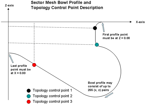
The piston-bowl shape must be provided in the form of a series of (X,Z) data pairs that have the following characteristics:
The first profile point must have Z = 0. This is the location of the outer edge of the bowl.
The remaining profile points must track the shape of the bowl towards the center of the cylinder, or towards the z-axis. This means: with decreasing X values.
The final profile point must have X = 0. This is the center of the bowl and a point of symmetry for the sector.
The indices of three of the profile points will be used to control the mesh topology as shown in the Figure 3.9: Sector mesh bowl profile and topology control point description.
For each control point, you must enter the fractional distance along the profile curve that corresponds to the location desired for that control point.
Once all of the parameters are specified, press the
Apply button in the Mesh Generator dialog to generate the mesh. The basic
outline of the cylinder geometry will be displayed within the Ansys Forte Sector Mesh Generator 3-D
View area, including the bowl profile and locations of control points. To create and load the
mesh, click the Generate Mesh  icon. This will involve several smoothing steps as the Sector Mesh
Generator attempts to provide an optimal mesh for the given inputs. The number of smoothing
steps is an optional parameter specified in the panel, but the default is usually sufficient.
The resulting mesh will be loaded automatically and displayed in the Ansys Forte 3-D View. In this
way, you can modify settings and then re-generate a new mesh quickly to interactively see the
effects of the input parameters. When you are finished, click the button marked Open
in Forte to update the content of the current Ansys Forte project. The settings there
will be saved with the Simulation file, to allow revisiting the mesh at a later time.


