A Reference Frame can be defined as an entity under the Geometry node and can be accessed as a subpanel in many geometry-related Editor panels. It provides the ability to set a reference point and orientation, such as a plane aligned with a tilted intake valve. Once defined, this reference frame can be used in place of the global x-y-z coordinate system when defining points, directions and velocities in the various Simulate Editor panels. Cartesian, spherical or cylindrical coordinate systems can be used when defining or referencing reference frames.
To create a reference frame, either specify the origin of the reference frame in the editor panel’s drop-down list as Global Origin, or create a new origin for the reference frame. Another way to create a new frame is to go to Geometry > Reference Frames on the Workflow tree and click the New Reference Frame button. Enter a distinctive name for the reference frame. It is added to the items on the Workflow tree. Specify the properties, including Origin, Coordinate System and coordinate values, and optional rotation.
Locations, such as the New Origin, can be specified by selecting
components in the 3-D window with the Select from screen
![]() button, by clicking the magnifying glass
button, by clicking the magnifying glass ![]() button to select an existing location from the list in the panel, or by
listing coordinates. Click Apply.
button to select an existing location from the list in the panel, or by
listing coordinates. Click Apply.
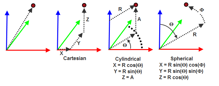
Note: The Z-axis always defines the primary axis for cylindrical and spherical coordinate point, direction, and velocity specifications.