


Use the Create Surface Mesh task to create a conformal, connected surface on all of the objects of an imported geometry, or remesh all or parts of an imported surface mesh. Use this task to identify regions that will later be filled with the volume mesh. In many cases, the default values will be sufficient for a useful CFD surface mesh.
You can generate your surface mesh based on settings defined in separate size control files or size field files. If you would like to use your own size field or size control files, provide an answer for the Use Custom Size Field/Control Files? prompt:
Choose No (the default) if want to proceed with setting surface mesh details in this task.
Choose Yes, size field file if you have a size field file to apply to the workflow. Select a Size Field File name when prompted. Enable the Preview Size Field check box to visualize the size field in the graphics window.
If the size field contains a body of influence or a face of Influence, you cannot use the Size Field File option to create a surface mesh. In such cases, you should provide the corresponding size control file.
Choose Yes, size control file if you have a size control file to apply to the workflow. Select a Size Control File name when prompted.
Choose Yes, both files if you have both a size field and a size control file to apply to the workflow. Select a Size Field File name and a Size Control File name when prompted. Enable the Preview Size Field check box to visualize the size field in the graphics window.
Size control files are described in Size Control Files. Size field files are described in Size Field Files.
If you chose to import a surface mesh in the Import Geometry task (Importing Geometries), you are prompted to indicate which portions of the surface mesh you want to remesh in this task.
If you have not assigned local sizing in the Add Local Sizing task (Adding Local Sizing)::
Choose All (the default) so that all surfaces will be re-meshed with the settings from this task.
Choose Selected where you can select specific faces or zones from a list for remeshing. Using this option, you cannot select all surfaces. In such cases, use the All option.
Choose None so that no faces or zones re-meshed in this task.
Note: Changing the mesh size on an imported mesh will always require a local size control.
If you have assigned local sizing in the Add Local Sizing task (Adding Local Sizing):
Choose All (the default) so that all surfaces will be re-meshed with the settings from this task.
Choose Assigned in Local Sizing to remesh only the boundaries that were assigned in the Add Local Sizing task. Enable the Preview Assigned Local Sizing check box to see a preview of those previously assigned boundaries.
Choose Assigned in Local Sizing and Selected to remesh those assigned boundaries from the Add Local Sizing task, as well as any other boundaries selected in this task. Enable the Preview Assigned Local Sizing check box to see a preview of those previously assigned boundaries.
Note: Adjacent zones are always included with assigned local sizing zones, such that Assigned in Local Sizing and selected includes boundaries assigned in the Add Local Sizing task, their adjacent zones, as well as the selected boundaries in this task.
Set the Minimum Size of the facets for the surface mesh.
Note: Clicking in this field displays red boxes in the graphics window, providing a visual representation of the field value. Use the Clear Preview button to hide the visualization display.
Set the Maximum Size of the facets for the surface mesh.
Note: Clicking in this field displays red boxes in the graphics window, providing a visual representation of the field value. Use the Clear Preview button to hide the visualization display.
Specify the Growth Rate.
Choose a Size Function.
The Curvature size function can be used for refining the surface mesh based on the underlying curve and surface curvature.
The Proximity size function can be used for creating the surface mesh, based on the number of cells per gap specified.
By default, a Curvature and Proximity size function is assigned based on both curvature and proximity.
Note: If local sizing has been added, these curvature and proximity size controls are appended to the local sizes and the resulting size field is used to dictate the sizes during surface meshing.
For additional information, see Size Functions and Scoped Sizing.
For the Ignore Proximity Across Objects? option, determine if you would like to ignore any small artificial gaps that may exist between two objects/bodies; especially applicable to assemblies that typically have duplicate faces and edges in between each body. These duplicate edges and faces may lead to additional artificial refinement and additional expense. Setting this option to Yes will effectively create a single proximity control for each body, eliminate artificial gaps, and improve performance.
Note: Using this option is strongly recommended if you intend to use the Interface Connect method in the Share Topology task (Applying Share Topology).
For the Curvature or the Curvature and Proximity size functions, specify the Curvature Normal Angle for the curvature size function. The default value of 18 degrees should approximately produce 20 facets in the circumferential direction of a cylinder.
For the Proximity or the Curvature and Proximity size functions, specify the Cells Per Gap for the proximity size function. This value is the number of element layers to be generated in a gap for the edge proximity size function. Note that for proximity size functions, the number of cells per gap can be a real value, with a minimum value of 0.01. See Proximity for more information.
For the Proximity or the Curvature and Proximity size functions, choose the Scope Proximity To value for the proximity size function, which can be scoped to edges, faces, or both faces and edges.
Select the Draw Size Box field to visualize the size control's minimum and maximum sizes in the graphics window (in the form of red cubes).
Use the Separate Out Boundary Zones by Angle? option to determine whether or not to separate face zones. By default, this is set to No.
If set to Yes, separation is based on a specified separation angle. Separation is needed in case named selections for inlets, outlets, capping, local boundary layers, etc. have not been defined within the CAD model in advance. You should only select Yes if you need to separate faces for capping, boundary conditions, or inflation on specific faces. Use the Separation Angle option to specify a desired angle for determining separation. Assigning a smaller separation angle will produce more zones.
Note: You will have the option to re-merge zones in the Generate the Volume Mesh task (see Generating the Volume Mesh).
If you want to remesh a portion of the imported surface mesh (by choosing selected for the Which boundaries do you want to remesh? prompt), you can select an available zone or label to apply your remeshing changes.
Choose whether to Select By the label or zone name in the list below.
Note: Labels originate from the CAD geometry, such as from group names in SpaceClaim geometries, or from named selections in DesignModeler geometries.
Select items in the list, or use the Filter Text option in the drop-down to provide text and/or regular expressions in filtering the list (for example, using *, ?, and []). You can also choose the Use Wildcard option in the drop-down to provide wildcard expressions in filtering the list. When you use either
?or*in your expression, the matching list item(s) are automatically selected in the list. Use^,|, and&in your expression to indicate boolean operations for NOT, OR, and AND, respectively. See Filtering Lists and Using Wildcards for more information.Click Advanced Options to access additional controls prior to performing this task. For additional information, see Face Connectivity Issues and Quality Checking. Options include:
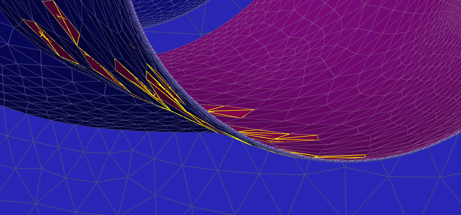
Use the Check Self-Intersection? field to determine whether or not the system will check for self-intersecting faces as part of the surface mesh creation. This check will, for example, detect if share topology has been omitted. For larger models, this check, however, can be time consuming, so if a model initially passes this test the first time, it can be safely disabled.
Figure 3.2: Example of a Self-Intersection: Local Mesh Size is Significantly Larger Than the Pipe Thickness
Note: Importing a surface mesh naturally involves a limited amount of topological information (as opposed to directly importing a CAD geometry), thereby making it difficult to determine when you can, or when you want to, use share topology. Note that while share topology can be detected using the Check Self-Intersection? field. This option, however, tends to be computationally expensive for large meshes. When trying to determine when to, or when not to, use share topology, consider the following scenarios:
If you do not know if share topology is required: enable the Check Self-Intersection? option (with default settings), and share topology will be automatically enabled.
If you know that share topology is required, but you would like more control of the settings: disable the Check Self-Intersection? option, and manually enable the Apply Share Topology task (Applying Share Topology.
If you know that share topology is not required: disable the Check Self-Intersection? option, and do not enable the Apply Share Topology task. This is useful to consider when, for example, you have a large mesh and do not want to incur the computational expense of using the Check Self-Intersection? option.
Note that these same scenarios apply even if you are using a CAD plug-in instead of a CAD reader.
Use the Smooth Folded Faces/Repair Free Nodes Limit option to provide a value limiting when folded faces are resolved during surface mesh creation.
Use the Auto Assign Zone Types? option to automatically assign boundary types to zones during surface mesh creation. For example:
If the Boundary Name Contains... ...Assign Boundary Type to... *mass*inlet* mass flow inlet *inlet*vent* inlet vent *press*inlet* pressure inlet *inlet* velocity inlet *mass*outlet* mass flow outlet *outlet*vent* outlet vent *outlet* pressure outlet *intake*fan intake fan exh*fan* exhaust fan *fan or *fan.* or *fan:* or *fan_ fan *symmetry* symmetry *far*field* pressure far field *outflow* outflow *porous*jump* porous jump *radiator* radiator *overset* overset *internal* or *interior* internal *interface* interface Note: In addition, only exterior boundary zones are assigned to corresponding external boundary types (that is, an interior zone named "inlet" will not be assigned to a velocity-inlet boundary type).
Use the Invoke Quality Improve? option to choose whether or not quality measures are applied during surface mesh creation. Surface mesh quality improvements should be invoked after importing the CAD model.
When Invoke Quality Improve? is enabled, an attempt will be made to improve the quality on those triangles where the skewness is above the Quality Improve Skewness Limit.
When Invoke Quality Improve? is enabled, four consecutive attempts are made to improve the quality, each using a larger adjacent angle, until the Quality Improve Max Angle.
When Invoke Quality Improve? is enabled, and after quality improvements, using the Quality Improve Skewness Limit and Quality Improve Max Angle are complete, if any remaining triangles are above the Quality Improve Collapse Skewness Limit value, these triangles will be aggressively removed using a fixed maximum angle of 120 degrees.
When using bodies of influence (for example, body sizing, local refinement regions, etc.), you can use the Set Volume Mesh Max Size? prompt to determine whether or not you need to assign a maximum size for the volume mesh. By default, this is set to no, however, when set to yes, you can then specify a value for the Volume Mesh Max Size, and eliminate the need for Fluent to perform additional size function calculations when generating the volume mesh.
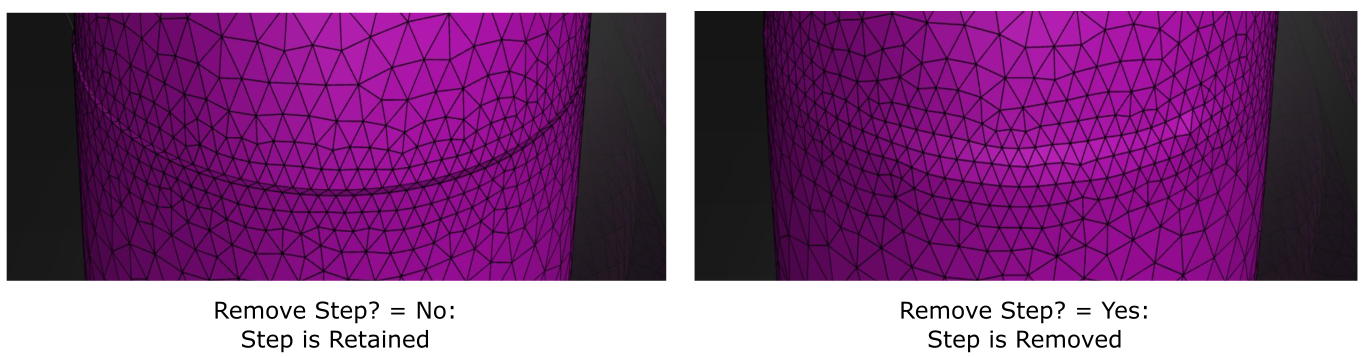
Use the Remove Steps? prompt if there are any small imperfections (ledge or step artifacts from the original CAD geometry) that can be removed as part of the surface meshing task. If you specify yes, then you need to indicate the Max Step Width.
For example, a typical 90 degree step artifact can be removed and replaced with a flattened mesh, removing any artificial pressure loss. Since this is performed before auto-remeshing, some coarsening may occur locally.
Step removal only occurs if the step(s) and the adjacent triangles belong to the same face zone or the same label, therefore, there are ways to protect steps from being removed:
Adding a label to the step itself (or to a face adjacent to the step) will protect the step from being removed.
Zone separation will protect all steps.
Note: All steps within a zone (or within a label) are checked and treated together, therefore it is enough that one step in a zone has a label adjacent to it in order to protect all steps.
This can also be performed as part of improving the surface mesh (see Improving the Surface Mesh).
In other words, steps can only be removed under the following conditions:
The step, and adjacent faces, does not belong to any named selection
The step, and adjacent faces, belongs to the same named selection
In some cases, you should consider disabling the quality improvement option in the task so that you obtain a "cleaner" step removal.
Use the Auto Remesh to Remove Clustering? option to automatically remesh the surface mesh to remove excessive clustering of nodes.
For imported mesh files, the auto option will not remesh by default. Remeshing will only occur if you are remeshing all faces and have set the Auto Remesh to Remove Clustering? option to yes.
For imported size field files, the auto option will not remesh by default, and you should set the Auto Remesh to Remove Clustering? option to yes.
For all other cases, using the default of auto will only invoke automatic remeshing if the Add Local Sizing task has been added to the workflow.
Alternatively, you can use the much faster refaceting technique rather than the automatic remeshing technique for the surface mesh by selecting no, use re-faceting for the Auto Remesh to Remove Clustering? option. This is particularly useful for thin volume meshing driven by face-face proximity where the original faceting is not fine enough to provide an accurate mesh size.
Click Generate the Surface Mesh to generate a CFD surface mesh for the imported CAD geometry.
During the process of creating the surface mesh for an imported CAD assembly geometry containing multiple parts, Fluent can detect whether or not the geometry has shared topology enabled. If the imported geometry does not have shared topology enabled, Fluent will provide your workflow with a Shared Topology task (within the Describe the Geometry task, see Applying Share Topology) where you can identify and close any problematic gaps and choose whether to join and/or intersect the problematic faces.
When the Shared Topology task is used, the following advanced options for the Generate the Surface Mesh task are actually performed at the end of the Shared Topology task:
Automatic zone separation
Automatic remesh to remove clustering
Final surface mesh improvement
Note: An assortment of information and messages appear in the console when the task is complete. For instance, for imported CAD geometries that include body labels (and if you have set the Use Body Labels field to Yes in the Import Geometry task, see Importing Geometries), statistics such as skewed cells, average and maximum skewness, and face count for available body labels are listed for you to review.
If you need to make adjustments to any of your settings in this task, click Edit, make your changes and click Update, or click Cancel to cancel your changes.
Proceed to the next step in the workflow.
Additional quality improvements can be made to surface meshes using the Improve Surface Mesh task (see Improving the Surface Mesh).