


During the process of creating the surface mesh for an imported CAD assembly geometry containing multiple parts, Fluent can detect whether or not the geometry has shared topology enabled. If the imported geometry does not have shared topology enabled, Fluent will provide your workflow with an Apply Share Topology task (within the Describe the Geometry task) where you can identify and close any problematic gaps and choose whether to join and/or intersect the problematic faces.
In an assembly, each individual body contains all of its faces, none of which are shared with another body, therefore making the model "non-conformal" to Fluent, where special handling is required for the solver. By performing the task, all bodies in contact will share faces across bodies, and the model is made "conformal" therefore making the model compatible with the Fluent solver.
Note: When ANSYS SpaceClaim DesignModeler cannot perform a Force Share
operation, the problematic faces are identified as specifically named selections (for
example, Connect Topology 25 or Connect Topology
100, and so on). You can use such partially shared topologies within the
workflow, however, you must retain those specifically named selections - you should
not remove or rename them.
Note: You must resolve acute face-face angles using fillets before attempting any share topology operation, since these could otherwise be unintentionally collapsed.
Specify a value for the maximum gap distance (either Max Gap Distance for Join-Intersect or Max Gap Distance for Connect depending on the Share Topology Method).
Click the Show Marked Gaps button to identify gaps that are less than the gap distance.
Note: The maximum gap distance should be equal to or less than half of the value specified for the Minimum Size in the Generate the Surface Mesh task. Also, the maximum gap distance should never exceed the thickness of a solid or fluid body, otherwise the solid or fluid bodies may potentially collapse.
Note: You should be cautious when setting an appropriate Minimum Size for the surface mesh. Using an unnecessarily small minimum size value, relative to the gap distance, may cause problems generating a successful Share Topology task.
See Troubleshooting Gap Marking for more information.
For the Share Topology Method, keep the default value of Join-Intersect in order to join and/or intersect the problematic faces, or choose Interface Connect in order to connect edges of overlapping face pairs, providing potential increases in speed and robustness.
Note: When using the Interface Connect method, it is strongly recommended that you also use the Ignore Proximity Across Objects? option in the Create Surface Mesh task (Generating the Surface Mesh).
Note: Since the Interface Connect method uses both edge stitching and the join operations to resolve overlapping faces, the Interface Connect method will still locate the overlapping faces and attempt to join them even if labels have not been assigned to some overlapping face pairs.
In addition, note that imprinting of overlapping faces in SCDM/Discovery is highly recommended for the Interface Connect method.
Click Advanced Options to access additional controls prior to performing this task. Options include:
For the Interface Connect share topology method, use the Interface Labels Selection Method to determine how interface labels are to be selected when using the Interface Connect share topology method. Options include:
Automatic - Using Connect Topology (available when force share connect topology is utilized in the SCDM geometry) will automatically use the labels where connect topology is used. In SCDM, these labels are of the form
Connect Topology1, and so on. Fluent translates them into the workflow and processes the labels asconnect-topology1, and so on, before finally being removed once the Share Topology task is complete.Manual allows you to manually select the interface labels from the list of available labels. This option lets you select both the connect topology labels as well as any specific labels that you need to retain (for example, if you have defined connect topology labels in SCDM but you want to retain some interfaces and keep specific labels for later re-use in the solver or post processing).
Automatic will automatically separate face zones, identify overlapping faces, and assign the interface connect labels. This option is useful when connect topology has not been utilized in Ansys SpaceClaim Direct Modeler (SCDM) or if the mesh was obtained from another source, such as Ansys DesignModeler (DM). Performance, however, may be impacted.
Note: Zones are separated during the automatic interface connect, however, they will be merged back after the volume mesh is generated.
When using the Interface Connect share topology method, for the Will You Set Up Periodic Boundaries? prompt, select yes if periodic boundaries are present. Select the appropriate periodic boundaries from the list since these boundaries need to be treated differently in this task.
For the Join-Intersect share topology method, use the Join Pair Normal Angle option to specify the feature angle to identify features in the overlap region.
Use the Initial Relative Tolerance option to specify the tolerance value (relative to face edges) for locating the overlapping faces. This is the relative tolerance for joining or intersecting face pairs, or the relative tolerance for connecting edge and face pairs.
For the Join-Intersect share topology method, use the Number of Join Attempts option to control the number of times the task attempts to join faces within the gap.
Use the Join Tolerance Increment option to control the change in tolerance with each join attempt.
For the Join-Intersect share topology method, use the Join and Intersect Method option to control whether the gap faces are joined, whether they are intersected, or both.
Use the Rename Internals Based on Body Names? prompt to determine whether you will apply body names from the imported geometry and use them in naming internal boundaries. For instance, the internal face between two regions "solid" and "body" would be renamed to "solid-body".
Note: The Initial Relative Join Tolerance can be aggressive, in relation to the Number of Join Attempts, so increasing the number of attempts may yield better results for certain circumstances. In addition, improvements are possible if you cross-imprint overlapping faces within SpaceClaim so that you have one-to-one face matching.
Once your selections are made, click the Apply Share Topology button and proceed to the next task.
The task locates and joins problematic face gaps and intersections through a series of incremental attempts until the geometry exhibits the equivalent of shared topology.
If you need to make adjustments to any of your settings in this task, click Edit, make your changes and click Update, or click Cancel to cancel your changes.
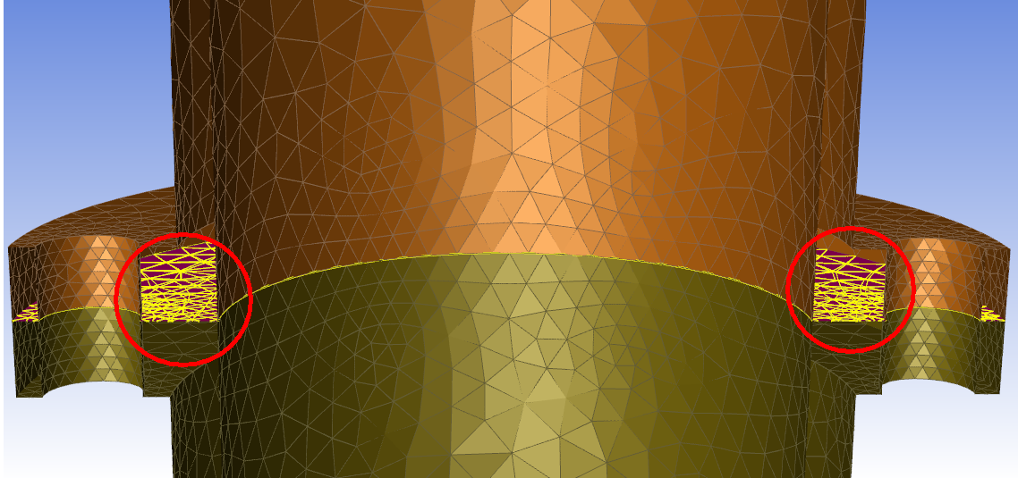
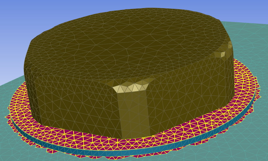
In the Shared Topology, use the Show Marked Gaps button to display any gaps in the geometry less than the maximum gap distance size. Gaps between object pairs are identified and highlighted in the graphics window.
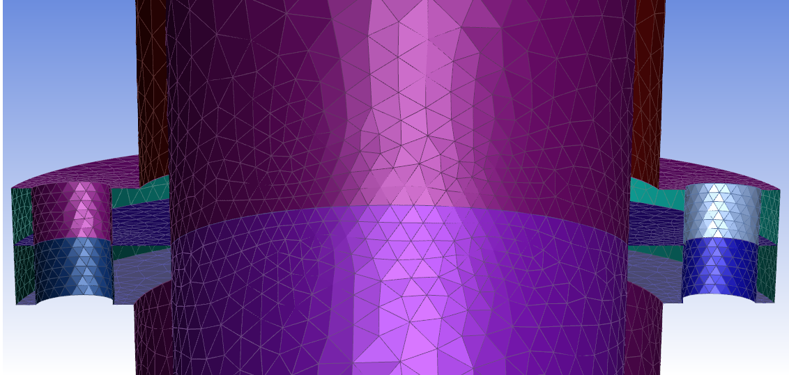
Once marked, you can select the Apply Share Topology button to update the task and view the final results. Based on the task's default settings, pairs are processed and joined and/or intersected according to various tolerances over a number of incremental steps, until all identified pairs are successfully processed and all gaps between parts are closed.
In some cases, sporadic gap markings are possible when the maximum gap distance is not sufficient:
Improvements can be made by adjusting the maximum gap distance accordingly.
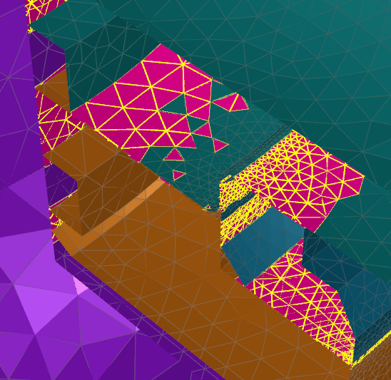
Additionally, using a value for the gap distance that is too aggressive may lead to a collapse of the geometry entirely once the task is updated.
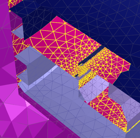
Slight readjustments of the maximum gap distance in accordance with the minimum size can be successful:
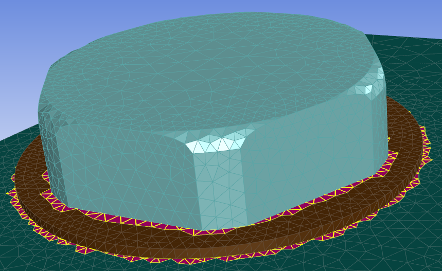
In some case, you may be required to adjust and re-adjust the value of the maximum gap distance field so that all gaps are properly identified and closed.