


Use the Import Geometry task to designate a geometry or surface mesh for your simulation.
Use the File Format field to choose either a CAD geometry, or a surface or volume Mesh format.
Note:
Do not use the workflow to import a surface mesh that was previously generated and saved from another workflow using a CAD geometry. You should only load previously generated meshes using the File > Read > Mesh option.
If you must use such a model in the Watertight Geometry workflow, you should first read the previously generated mesh using the File > Read > Mesh option, use the Outline View to delete the geometry object that corresponds to the mesh object, and save the mesh before reading it into the Watertight Geometry workflow.
When the File Format is set to CAD, use the Import Type field to import a Single File (the default), or Multiple Files. When importing multiple files, the Select File dialog allows you to make multiple selections, as long as the files are in the same directory and are of the same CAD format.
If a Mesh format is chosen, specify the File Unit in which the mesh was created.
The workflow will display the units in the graphics window next to the ruler and while calculating distances (for example, when using the Distance tool in the Ribbon).
Choose a suitable option for the Units. You should work in units where the minimum size of the mesh is of the order of one. The mesh will automatically be scaled to meters while transferring the mesh to the Fluent solver
If the CAD format is chosen, set the Use Body Labels field to Yes when the CAD geometry contains body labels that you want to use. As the geometry is read in, if the CAD geometry does not contain any body labels, then this field will automatically be set to No.
Note:When named selections in the CAD geometry are assigned to only a single body, the workflow supports such body labels in lists and tables.
When the Use Body Labels option is set to Yes, then the workflow additionally supports "composite body labels" that occur when named selections in the CAD geometry are assigned to multiple bodies.
The workflow also lists bodies for which no (or a single) body label has been defined as well as any newly created regions.
A named selection added to a surface body in CAD might not always be recognized as a label in the Update Boundaries task.
Click Advanced Options to access additional controls prior to performing this task. Options include:
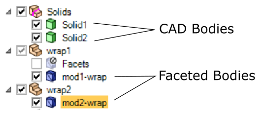
In some CAD environments (for example SpaceClaim, DesignModeler, or Discovery), faceting and wrapping operations lead to non-CAD geometries that cannot be directly used in the workflow. In such cases, you can set the Model includes shrink-wrapped bodies? prompt to yes to properly manage such geometries. In such cases, all faceted bodies should only have names that end with "
*wrap" (or the default of "shrinkwrap"), and other bodies should not use such a naming convention.Note: You should shrink wrap any faceted bodies to ensure a relatively good quality surface mesh. In addition, each shrink-wrapped faceted body should be defined in its own unique component within the CAD environment.
If a Mesh format is chosen, use the Automatic Object and Label Creation? prompt to determine whether or not mesh objects and labels are automatically created upon import, potentially and dramatically increasing the mesh import speed for very large cases. By default, this is set to yes however, if it is set to no, then no labels are created and a single mesh object is created employing all zones.
Note: Zones that contain the string "boi" are excluded from object creation.
Use the Separate Zone By option to determine how zones are separated, either by region alone, by region as well as a specified separation angle, by face/edge topology, or none. Zone separation is necessary if local sizing must be applied. Region separation is sufficient for body sizing and/or body of influence, while separation by angle is needed for local face sizing. Separation by face will preserve the face/edge topology so that individual faces and edges can be selected when setting up a multizone mesh.
When Separate Zone By is set to region & angle, set the Separation Angle to a value for which CAD zones are separated. The lower the value for the angle, the higher the number of faces that will be separated. The default value is 40 degrees.
When Separate Zone By is set to face, edge labels will be created automatically on all edges, preserving the face/edge topology so that these individual entities can be selected while setting up a multizone mesh (see Adding Multizone Controls). Zones are automatically merged back on a body/region level after volume meshing. If Separate Zone By is set to none (the default), the face and edge topology will be merged together while importing the CAD geometry.
Note: For models where only a small portion is to be used for multizone meshing, this option is not recommended since creating and sharing edge labels can be computationally expensive.
In addition, when Separate Zone By is set to face, note the following:
You will no longer are able to separate zones based on angle (see Generating the Surface Mesh).
Multizone meshing will not work if you have edges contained within a face with no angle between them and adjacent faces
All named selections on edges defined within the CAD model will be ignored.
You can no longer insert or use the Manage Zones task prior to generating the volume mesh (see Managing Zones).
Enable Use custom faceting in order to set the following faceting options for your imported geometry:
Set the Tolerance (10% of min-size) value, however, using the default value of 0 results in the coarsest possible faceting.
Set the Max Facet Length value to avoid very large facets during file import.
Browse for a specific File Name.
Supported file types are SpaceClaim (
.scdoc), Discovery (.dsco), and Workbench (.agdb) files and also.pmdbfiles.Note: When a SpaceClaim (
.scdoc) file is imported into Fluent while in meshing mode, Fluent also creates an intermediary.pmdbfile that can be imported. The.pmdbfile should always reside alongside the.scdocfile. When changes are made to the geometry in SpaceClaim, and the file is reimported into Fluent, the original.pmdbfile is overwritten. The.pmdbfile can be more easily and quickly read into Fluent for additional processing and should be used as long as the.scdocfile has not changed.Note: SpaceClaim (
.scdoc) files are only supported on Windows. When working on Linux systems, however, you can use the intermediary.pmdbfile as your geometry file for the workflows.On Windows, use the Import CAD Geometry dialog to import the CAD file into Fluent, and enable the Save PMDB (Intermediary File) option in the Import Options dialog. After the file is imported, you can move the generated
.pmdbfile over to your Linux system to use in your workflow.If you have manually entered a CAD geometry file name, click Import Geometry, otherwise the task is automatically performed if you browse and select a CAD file.
If you need to make adjustments to any of your settings in this task, click Edit, make your changes and click Update, or click Cancel to cancel your changes.
Proceed to the next step in the workflow.