


You can gain better control over the mesh size distribution by using the Add Local Sizing task. Using this task, you can define specific mesh size controls that operate on specific, localized, portions of the geometry and mesh. Using this task, you can add as many localized size controls to the workflow as you need, depending on the requirements and details of your geometry. Note that this task can only be added to the workflow prior to the Generate the Surface Mesh task.
For the Would you like to add local sizing? field, select yes if you need to define local sizing parameters using the following steps. Otherwise, if you do not need to define local sizing controls, keep the default of no, click Update and proceed to the next task.
Provide a Name for the new size control, or use the default name. The default name changes depending on the assigned Size Control Type.
Provide a Growth Rate.
Choose the Size Control Type. Choices include:
Use the Edge Size setting for refining the local sizing based on the edge size. This option is only available if the imported geometry contains one or more named edges (for example, an ANSYS SpaceClaim Design Modeler CAD geometry with one or more edges explicitly using named selections).
Use the Face Size setting for refining the local sizing based on the face size.
Note: For imported CAD geometries that include body labels (and if you have set the Use Body Labels field to Yes in the Import Geometry task, see Importing Geometries), available body labels are listed in the task for you to select (they are not selectable, however, from the graphics window).
Use the Body Size setting for refining the local sizing based on the body size.
Note: For imported CAD geometries that include body labels (and if you have set the Use Body Labels field to Yes in the Import Geometry task, see Importing Geometries), available body labels are listed in the task for you to select (they are not selectable, however, from the graphics window).
Use the Body of Influence setting, or BOI, to assign a maximum size on all parts of your geometry that falls within the boundaries of the body of influence.
Note: For a body that is associated with a Body of Influence (BOI body), keep the following in mind:
The BOI body must not share topology with the CAD model itself within SCDM or DM.
The BOI body must have a unique name within SCDM or DM.
All imported BOI bodies must be assigned a local sizing control.
You can enable the Repair Body of Influence option in the rare case that the initial body of influence is not fully closed.
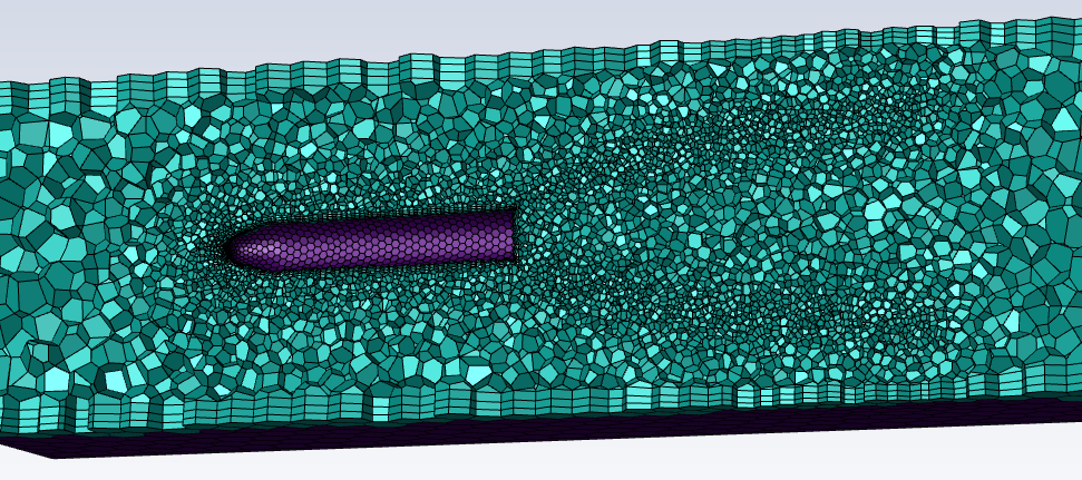
Use the Face of Influence setting, to assign a maximum size on all parts of your geometry that falls within the boundaries of the face of influence. A face of influence is essentially a body of influence on a non-closed, non-connected face (for example, a surface representing the wake behind a moving object).
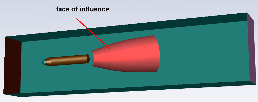
The face is deleted during surface meshing, however the mesh refinement is visible during volume meshing
Use the Curvature setting for refining the local sizing based on the underlying curve and surface curvature. This size control type is useful, for instance, in models with a combination of large and small scales.
Use the Proximity setting for refining the local sizing based on the number of cells per gap specified.
If you are using the Face Size, Body Size, Body of Influence, or Face of Influence size control type, provide a Target Mesh Size.
Note: Clicking in this field displays red boxes in the graphics window, providing a visual representation of the field value. Use the Clear Preview button to hide the visualization display.
Note: Ensure that the assigned size of the BOI is smaller than the BOI itself, and not perfectly aligned with the CAD model (or other BOI bodies), to avoid mistakenly invoking shared topology and associated warnings due to thin regions and soft size functions.
Keep in mind that even if you do not include the BOI bodies in the share topology, the share topology will still affect overlapping BOI bodies if the parent to the bodies have the Share Topology property enabled in SCDM.
If you are using the Curvature size control type, you have the following options:
Specify a value for the Local Min Size for the curvature size control.
Specify a value for the Max Size for the curvature size control.
Specify a value for the Curvature Normal Angle for the curvature.
Specify a value for the Scope to field, where you can localize the size control to faces, edges, faces and edges, or edge labels. Edge selection selects the edges of a particular face.
If you are using the Proximity size control type, you have the following options:
Specify a value for the Local Min Size for the proximity size control.
Specify a value for the Max Size for the proximity size control.
Specify a value for the Cells Per Gap. This value is the number of element layers to be generated in a gap for the edge proximity size function. Note that for proximity size functions, the number of cells per gap can be a real value, with a minimum value of 0.01. See Proximity for more information.
Specify a value for the Scope to field, where you can localize the size control to faces, edges, faces and edges, or edge labels.
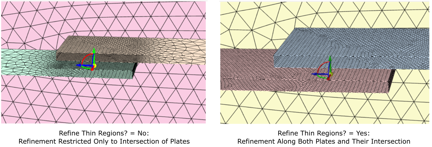
If you are using the Proximity size control type, and you Scope to either faces or faces and edges, use the Refine Thin Regions (Ignore Orientation)? field to determine if you need to additionally refine the mesh in and around thin areas such as between plates, without providing over-refinement. This ignores face proximity within voids and will not allow you to refine in thin voids, but will allow refinement in gaps. This should be used in predominantly fluid regions with no thin solid regions.
You can select an available zone or label to apply your local sizing changes. Choose whether to Select By the zone name, or the label name in the list below.
Note: Labels originate from the CAD geometry, such as from group names in SpaceClaim geometries, or from named selections in DesignModeler geometries.
Select items in the list, or use the Filter Text option in the drop-down to provide text and/or regular expressions in filtering the list (for example, using *, ?, and []). You can also choose the Use Wildcard option in the drop-down to provide wildcard expressions in filtering the list. When you use either
?or*in your expression, the matching list item(s) are automatically selected in the list. Use^,|, and&in your expression to indicate boolean operations for NOT, OR, and AND, respectively. See Filtering Lists and Using Wildcards for more information.Select the Draw Size Box field to visualize the size control's minimum and maximum sizes in the graphics window (in the form of red cubes).
Once your selections are made, click Add Local Sizing and proceed onto the next task.
You can add as many local sizing controls as you require for your workflow, each operating on different zones and/or with different sizing parameters. The size controls will appear as sub-tasks under the parent task.
If you need to make adjustments to any of your settings in this task, select the specific size control sub-task, click Revert and Edit, make your changes and click Update, or click Cancel to cancel your changes.
Note: If you need to add another local sizing control after you have already created a surface mesh, you need to revert and edit at least one existing local size control in order to properly see and use the available geometry objects in the graphics window and the object listing. Alternatively, you can also re-import your geometry and update the Add Local Sizing task.
Once you are satisfied with your changes, proceed to the next step in the workflow.