


You can use the Set Up Periodic Boundaries task to define rotational and/or translational periodicity in your simulation. This task essentially re-meshes a periodic face to exactly match the reference side of the face, as well as define the corresponding Fluent boundary types (periodic and shadow), in preparation for the Fluent solver. If your periodic simulation also involves shared topology (Applying Share Topology), you should first invoke the Apply Share Topology task prior to the Set Up Periodic Boundaries task.
Note: This task is not available when the Capability Level is set to Pro in the Fluent Launcher.
Note: This task can usually be added to your workflow after the Create Surface Mesh task, however, you are able to add this task before generating your surface mesh, albeit with some limitations (noted below). Specifically, you are limited to only being able to manually pick the periodic faces and only via labels. Benefits can include, for example, that for large models, where the size function calculation is very time consuming, and when the mesh density is asymmetric between the periodic sides, inserting the periodicity setup task before generating the surface mesh will avoid an additional size function calculation.
In addition, you cannot use the Manual - pick reference side option to apply periodicity when you have zones that consist of multiple, detached regions. Using the Automatic - pick both sides option (along with using labels) separates these zones into individual regions on both sides, allowing for a successful set up and recovery of the periodic boundary condition.
Multiple instances of the Set Up Periodic Boundaries task can be inserted into the workflow for defining multiple periodic conditions. Additionally, automatic multiple periodic setup is provided for setting up a translational periodic boundary with multiple periodic pairs.
Note: The following limitations apply when defining multiple periodic conditions or when using automatic multiple periodic setup:
You cannot have two different periodic boundaries sharing an edge.
The combination of multiple periodicity and multizone meshing within a single region is not supported.
Automatic multiple periodic setup can only be used to define Translational periodic boundaries and Automatic - pick both sides must be selected for the Method.
Use the Type field to choose whether you are creating Rotational or Translational periodic boundaries.
Note: In order to ensure the recovery of translational periodicity, you should also apply a local proximity size control on periodic surfaces (with a Cells Per Gap setting of 2).
Use the Method field to choose how you are going to define your periodic boundary. This option is not available when this task is added to the workflow before the Generate Surface Mesh task: the manual method is all that is available.
Choose Automatic - pick both sides to define the periodic boundary based on your zone/label selections
Note: When using this option, you must select two zones or labels.
Choose Manual - pick reference side to manually assign properties of the periodic boundary.
Note: When using this option, you only need to select a single zone or label.
You would use this option in the following situations:
You already know the periodicity angle, or translational shift, the components of the origin, and the components of the vector, and which side is the reference side.
All your periodic faces are non-planar.
The mesh is asymmetric on the two periodic faces, and you need to use the side with the refined mesh as a reference.
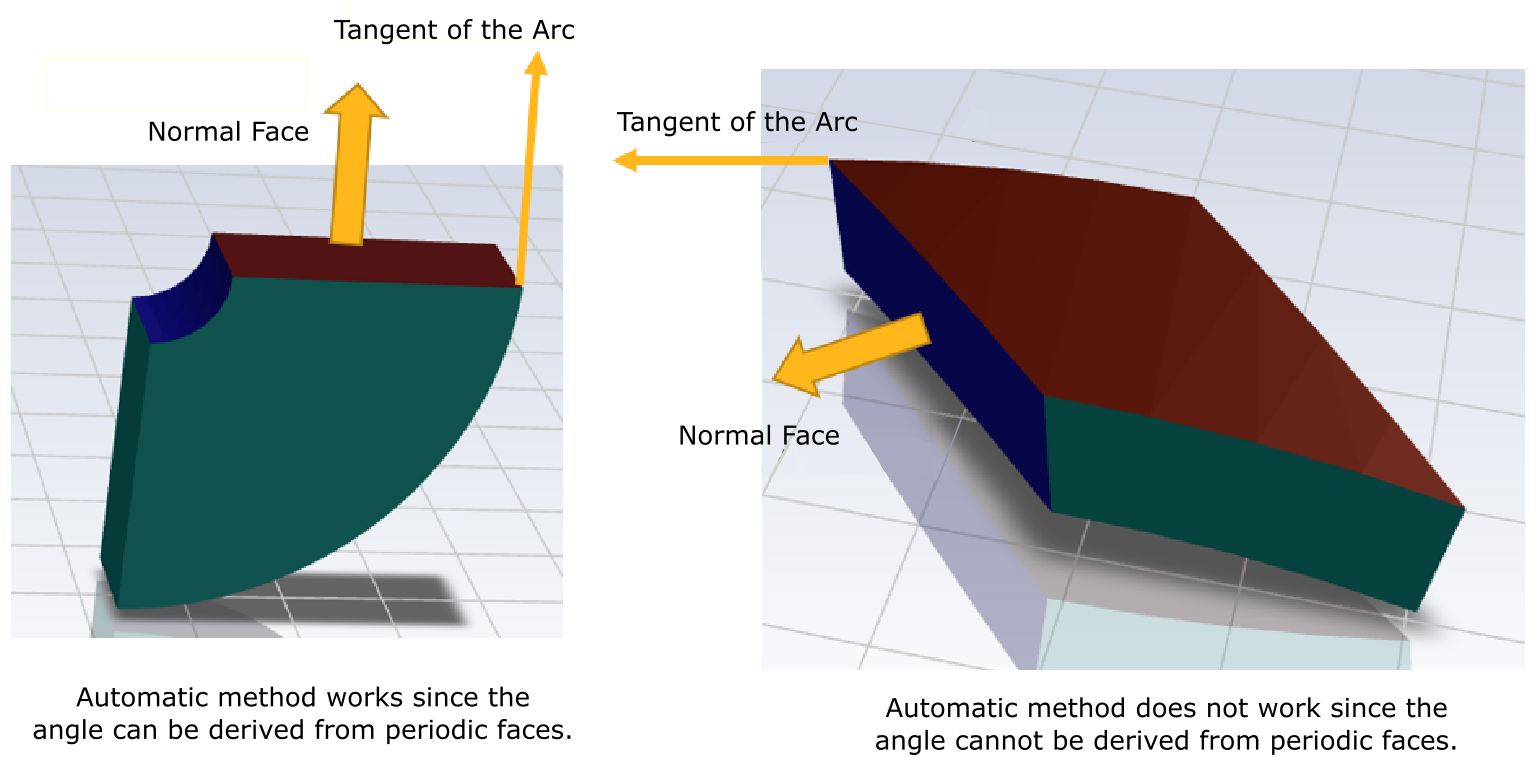
Note: There are two scenarios when the Automatic - pick both sides method is not able to derive the periodicity parameters:
when there are no planar faces, and
when the normal of the planar faces do not align with the tangent of the arc of the circle sector.
For rotational periodicity, the Automatic - pick both sides method may not accurately derive the correct periodicity parameters when the periodicity angle is small (for example, smaller than ~10 degrees), in which case, the Manual - pick reference side method is recommended. Additionally, the periodicity angle is best measured (in SCDM for instance) using the geometry's arc angle and arc radius rather than using the angle between objects and their minimum distance.
For rotational periodicity:
Specify a value for the Periodicity Angle.
For the Origin Components, specify a value for X, Y, and Z.
For the Vector Components, specify a value for X, Y, and Z.
For translational periodicity, under Translational Shift, specify a value for X, Y, and Z.
Choose whether to Select By the zone name or the label name in the list below.
Note: Labels originate from the CAD geometry, such as from group names in SpaceClaim geometries, or from named selections in DesignModeler geometries.
Select items in the list, or use the Filter Text option to provide text and/or regular expressions in filtering the list (for example, using *, ?, and []). See Filtering Lists and Using Wildcards for more information.
If your model consists of multiple translational periodic pairs, you can select yes for the Are you using the Automatic Multiple Periodic Setup? option to automatically define the periodicity for multiple periodic pairs.
When set to yes, the Tagging method for Automatic Multiple setup option becomes available for specifying how the periodic pairs will be identified. If your model has one named selection for each periodic pair, you should select the Paired option, which is the default selection. If your model contains either of the following, you should select the Alphabetical option:
If your model contains one named selection at each side of the model in alphabetical order.
If your model contains one named selection for all periodic surfaces and one named selection for all shadow surfaces.
(optional) Use the Remesh Asymmetric Mesh Boundaries field to determine whether to remesh boundaries when there is an asymmetric mesh on the periodic faces: auto will let the system determine the best course of action, yes will permit the remeshing of the boundaries when the task is updated, and no will not remesh the boundaries.
(optional) By default, the table only lists external wall boundaries. When using labels, you can select the List All Labels check box to see additional boundary labels, such as fluid-fluid internal boundaries.
Once your selections are made, click the Set Up Periodic Boundaries button and proceed to the next task.
Once the task is completed, you will see an indicator in the graphics window showing the origin and vector, as well as updated mesh, where you can verify that the periodic sides have identical meshes. When the automatic option is used, the console displays the calculated periodicity angle, origin components, and vector components for future reference.
If you need to make adjustments to any of your settings in this task, click Edit, make your changes and click Update, or click Cancel to cancel your changes.
Note: If you return to the Set Up Periodic Boundaries task after creating a volume mesh, you can restore the visibility of the mesh by using the F2 hot key and either the Fit to Window icon (
 ) or the Draw Mesh button at the bottom of
the task.
) or the Draw Mesh button at the bottom of
the task.