


During a Fluent session, you may need to:
Read mesh, case, CAD, journal, Scheme, domain, and size-field files.
Write mesh, case, journal, transcript, and domain files.
Save pictures of graphics windows.
These files and operations are described in the following sections.
- 1.6.1. Shortcuts for Reading and Writing Files
- 1.6.2. Mesh Files
- 1.6.3. Case Files
- 1.6.4. Reading and Writing Size-Field Files
- 1.6.5. Reading Scheme Source Files
- 1.6.6. Creating and Reading Journal Files
- 1.6.7. Creating Transcript Files
- 1.6.8. Reading and Writing Domain Files
- 1.6.9. Importing Files
- 1.6.10. Saving Picture Files
The following features make reading and writing files convenient:
When you write a mesh, case, or size-field file, a binary file is saved by default. Binary files take up less memory than text files and can be read and written more quickly by Fluent.
To save a text file, disable the Write Binary Files option in the Select File dialog box when you are writing the file.
Fluent enables you to read and write compressed files. Use the Select File dialog box to read or write the files that have been compressed using compress or gzip.
If you select a compressed file with a .z extension, Fluent will automatically invoke zcat to import the file. If you select a compressed file with a .gz extension, Fluent will invoke gunzip to import the file. For example, if you select a file named flow.msh.gz, the following message will be reported, indicating that the result of the gunzip is imported into Fluent via an operating system pipe.
Reading "\" | gunzip -c \"Z:\flow.msh.gz\"\""...
When reading a compressed file using the text interface, you only need to enter the file name. Fluent first looks for a file to open using just the input name.
Note: For Windows systems, only files that were compressed with gzip (that is, files with a .gz extension) can be read. Files that were compressed using compress cannot be read into Fluent on a Windows machine.
You can use the Select File dialog box to write a compressed file by appending a .z or .gz extension onto the file name. For example, if you are prompted for a file name and you enter a file name with a .gz extension, a compressed file will be written. For example, if you enter flow.gz as the name for a mesh file, Fluent reports the following message:
Writing "| gzip -cfv > Z:\flow.msh.gz"...
The status message indicates that the mesh file information is being piped into the gzip command, and that the output of the compression command is being redirected to the file with the specified name. In this particular example, the .msh extension was added automatically.
Note: For case files, such
compression is not applied for the default Common Fluids Format (CFF), but instead the
.z or .gz extension is simply
incorporated into the name (such as .gz.cas.h5). This
compression is only used for the legacy format (such as when you have entered the
following text command: file/cff-files? no).
Note: For Windows systems, compression can be performed only with gzip. That is, you can write a compressed file by appending .gz to the name, but appending .z does not compress the file.
On LINUX systems, if you specify ~/ as
the first two characters of a file name, the ~ is expanded as your
home directory. Similarly, you can start a file name with
~username/, and the ~username is
expanded to the home directory of “username”. If you specify
~/file as the mesh file to be written, Fluent saves the file
file.msh.h5 in your home directory. You can specify a subdirectory of
your home directory as well: if you enter ~/examples/file, Fluent
will save the file file.msh.h5 in the examples
subdirectory.
By default, if you ask Ansys Fluent to write a file with the same name as an existing file in that folder, it will ask you to confirm that it is “OK to overwrite” the existing file. If you do not want Ansys Fluent to ask you for confirmation before it overwrites existing files, you can enter the file/confirm-overwrite? text command and answer no.
Mesh files are created using the mesh generators (Ansys Meshing, the meshing mode in Fluent, GAMBIT, GeoMesh, and PreBFC), or by several third-party CAD packages. From the point of view of Fluent, a mesh file is a subset of a case file (described in Case Files). The mesh file includes a list of the node coordinates, connectivity information that tells how the nodes are connected to one another to form faces and cells, and the zone types and numbers of all the faces (for example, wall-1, pressure-inlet-5, symmetry-2). The mesh file does not contain any information on boundary conditions, flow parameters. For information about the format of the CAD package files, see Appendix A: Importing Boundary and Volume Meshes, and for details on the mesh file format for Fluent, see Appendix B: Mesh File Format.
Note: You can also use the > > menu item to read a mesh file (described in Case Files) because a mesh file is a subset of a case file.
Important: If the mesh information is contained in two or more separate files generated by one of the CAD packages, you can read them one-by-one by selecting Append File(s) in the Select File dialog box. You can also read them together and assemble the complete mesh in the meshing mode.
Fluent can save the mesh files with the suffix .msh.h5. You need not type the suffix while saving the mesh file, it will be added automatically.
When using the file/read-mesh text command to read a
mesh file, Fluent first searches for a file with the exact name you typed. If a file with
that name is not found, by default it will search for a file with .msh.h5
appended to the name, and if a file with that name is still not found, it will search for a
file with .msh appended to the name.
To read a mesh, select > > to open the Select File dialog box and select the mesh file to be read.
Note: Reading mesh files also includes reading any associated boundary layer flags during the reading process (in order to identify prism cells when later appending any subsequent mesh files).
You can also use this option to read a Fluent mesh file created with GAMBIT, or to read the mesh contained in a case file.
In addition, you can read a mesh file by 'dragging and dropping' the file directly into an existing Fluent session.
By default, when reading mesh files, Fluent uses the Common Fluids Format (CFF) which is built on the Hierarchical Data Format (HDF5). To read CFF files, use the menu options or TUI commands and simply append .msh.h5 to the file name.
CFF and HDF files are always binary and make use of built-in compression. Thus, they cannot be viewed in a text editor. However, third-party tools are available that enable you to open and explore the contents of files saved in HDF format.
For reading legacy mesh files (.msh) in the current session, you
can use the file/cff-files? text command, answering
no to read legacy mesh files.
For reading legacy mesh files in future sessions, you can use the General category of the Preferences dialog, choosing Legacy for the Default Format for I/O option.
![]() File
→ Preferences...
File
→ Preferences...
Note: Reading a case file as a mesh file will result in loss of boundary condition data as the mesh file does not contain any information on boundary conditions.
Case files containing polyhedral cells can also be read in the meshing mode of Fluent. You can display the polyhedral mesh, perform certain mesh manipulation operations, check the mesh quality, and so on.
Important: You cannot read meshes from solvers that have been adapted using hanging nodes. To read one of these meshes in the meshing mode in Fluent, coarsen the mesh within the solver until you have recovered the original unadapted grid.
The /file/read-options command enables you
to set the following options for reading mesh files:
Enforce mesh topology: This option is disabled by default. Enabling this option will orient the face zones consistently when the mesh file is read. If necessary, the zones being read will be separated, such that each boundary face zone has at most two cell zones as neighbors, one on either side. Also, internal face zones are inserted between neighboring cell zones that are connected by interior faces.
Check read data: This option enables additional checks for the validity of the mesh. Enabling this option will check the mesh topology during file read. In case incorrect mesh topology is encountered, warning messages will be displayed and the erroneous entities will be deleted. Note that in case of mesh topology errors, no automatic mesh repair is done, and that parts of the mesh may be non-conformal, contain voids, or be erroneous in other ways. The purpose of the
check-read-dataoption is to enable access to corrupt files. This option is disabled by default with the assumption that correct data will be read, and to shorten file read times.
If the mesh is contained in two or more separate files, you can read them together in Fluent and assemble the complete mesh. For example, if you are creating a hybrid mesh by reading in a triangular boundary mesh and a volume mesh consisting of hexahedral cells, read both files at the same time using > > .
To read a Fluent boundary mesh (contained in a mesh file created with GAMBIT or in a Fluent case file) into Fluent, select > > to open the Select File dialog box and select the boundary mesh file to be read.
This option is convenient if you want to reuse the boundary mesh from a file containing a large volume mesh.
If the boundary mesh is contained in two or more separate files, you can read them in together and assemble the complete boundary mesh in Fluent.
You can read faceted geometry files (*.tgf) exported from Ansys Workbench in Fluent. To read the faceted geometry file, use > > or > > .
The naming of face zones can be controlled by Named Selections defined in Ansys Workbench. For details on exporting faceted geometry from Ansys Workbench, refer to the Ansys Workbench Help.
You can read multiple mesh files one by one instead of reading all of them at once. This process is called as appending the mesh files. To append files, read in the first mesh file using the Select File dialog box. Reopen the dialog box and enable Append File(s) and read the remaining files one by one.
Note: Append File(s) is not accessible while reading the first mesh file.
You can also append files using the command /file/append-meshes-by-tmerge, which uses the tmerge utility in Ansys Fluent. There is no graphical interface equivalent for this text command.
Append Rules:
If zone names and IDs are duplicated, they will be modified and the changes will be reported in the console.
Domain information will be retained during the file append operation. If domain names are duplicated, they will be modified and the changes will be reported in the console.
Refinement region information will be retained during the file append operation. If region names are duplicated, they will be modified and the changes will be reported in the console.
You can append files comprising only edge zones (without face zones).
Edge-face zone associations will be retained during the file append operation.
Zone-specific prism parameter information will be retained during the file append operation.
Boundary layer flag data is retained during mesh file reading and writing so as to identify prism cells during the append operation. In addition, boundary layer cell and face counts are reported during the append operation, and more generally, poly-prism counts are therefore available in the mesh statistics summary.
Nodal curvature data is read during the append operation.
To write a mesh file in the format that can be read by Fluent, select > > to open the Select File dialog box and specify the name of the mesh file to be written.
Note: Writing mesh files also includes writing any associated boundary layer flags during the writing process (in order to identify prism cells when later appending any subsequent mesh files).
By default, when writing mesh files, Fluent uses the Common Fluids Format (CFF) which is built on the Hierarchical Data Format (HDF5). To write mesh files using CFF, use the menu options or TUI commands and simply append msh.h5 to the file name.
CFF and HDF files are always binary and make use of built-in compression. Thus, they cannot be viewed in a text editor. However, third-party tools are available that enable you to open and explore the contents of files saved in HDF format.
For writing legacy mesh files in the current session, you can use
the file/cff-files? text command, answering
no to write legacy mesh files.
For writing legacy mesh files in future sessions, you can use the General category of the Preferences dialog, choosing Legacy for the Default Format for I/O option
![]() File
→ Preferences...
File
→ Preferences...
Depending on
your preference settings, the Select File dialog box will have a
default value for the field, either CFF files
(*.msh.h5) or legacy compressed files
(*.msh.gz), whereby you can just specify a file name (without the
extension) and Fluent will append the correct file extension accordingly.
See Binary Files for information about the file format.
The /file/write-options command enables you to set the enforce mesh topology option for writing mesh files. This option is disabled by default. Enabling this option will orient the face zones consistently when the mesh file is written. If necessary, the zones will be separated, such that each boundary face zone has at most two cell zones as neighbors, one on either side. Also, internal face zones will be inserted between neighboring cell zones that are connected by interior faces.
Note: You should delete dead zones in the mesh before writing the mesh or case file for Fluent.
Fluent enables you to write a mesh file comprising specific boundary zones. This is useful for large cases where you may want to mesh different parts of the mesh separately and then merge them together. This enables you to avoid frequent switching between domains for such cases. You can write out selected boundaries to a mesh file and then create the volume mesh for the part in a separate session. You can then read the saved mesh into the previous session using the Append File(s) option and merge the part with the rest of the mesh.
To write a mesh file comprising selected boundaries, select > > menu item to invoke the Write Boundaries dialog box and select the boundaries to be written.
Case files contain the mesh, boundary and cell zone conditions, and solution parameters for a problem. They also contain the information about the user interface and graphics environment. Fluent allows you to read and write either text or binary files, in compressed or uncompressed formats (For details, see Binary Files and Reading and Writing Compressed Files). Fluent automatically detects the file type when reading.
Important: Changing the ID of a thread in the meshing mode may affect the case set up. In such cases, you will be prompted to confirm that you want to proceed with the ID changing operation.
The commands used for reading case files can also be used to read native-format mesh files (as described in Mesh Files) because the mesh information is a subset of the case information. The commands for reading and writing case files are described in the following sections.
To read a case file, select > > to open the Select File dialog box and select the case file to be read.
In addition, you can read a case file by 'dragging and dropping' the file directly into an existing Fluent session.
By default, when reading case files, Fluent uses the Common Fluids Format (CFF) which is built on the Hierarchical Data Format (HDF5). To read case files using CFF, use the menu options or TUI commands and simply append cas.h5 to the file name. Alternatively, use the CFF Case Files option from the Files of type drop-down list in the Select File dialog box.
For reading CFF files in the current session, you can use the
file/cff-files? text command, answering
yes to read case files in the CFF format.
For reading CFF files in future sessions, you can use the General category of the Preferences dialog
![]() File
→ Preferences...
File
→ Preferences...
CFF and HDF files are always binary and make use of built-in compression. Thus, they cannot be viewed in a text editor. However, third-party tools are available that enable you to open and explore the contents of files saved in HDF format.
Note: Cell hierarchy in case files adapted in the solution mode will be lost when they are read in the meshing mode.
Case files containing polyhedral cells can also be read in the meshing mode of Fluent. You can display the polyhedral mesh, perform certain mesh manipulation operations, check the mesh quality, and so on.
Note: When you read a non-conformal interface case file into meshing mode and later switched to the solution mode, note the following limitations:
Zone ids may match, however, the corresponding zone names may be inconsistent.
Boundary conditions on intersected threads are not preserved.
Unassociated (dangling) non-conformal interface (NCI) surfaces remain present.
When reading case files, you can still use the legacy case file format. To read legacy case files, you can use the same menu options or TUI commands and simply append cas to the file name. Alternatively, select All Case Files from the Files of type drop-down list in the Select File dialog box.
For reading legacy files in the current session, you can use the
file/cff-files? text command, answering
no to read case files in the legacy format.
For reading legacy files in future sessions, you can use the General category of the Preferences dialog
![]() File
→ Preferences...
File
→ Preferences...
For the Default Format for I/O option, select Legacy to use the legacy file format.
To write a case file in the format that can be read by Fluent, select > > .
By default, when writing case files, Fluent uses the Common Fluids Format (CFF) which is built on the Hierarchical Data Format (HDF5). To write case files using CFF, use the menu options or TUI commands and simply append cas.h5 to the file name. Alternatively, use the default CFF Case Files option from the Files of type drop-down list in the Select File dialog box.
For writing CFF files in the current session, you can use the
file/cff-files? text command, answering
yes to write case files in the CFF format.
For writing CFF files in future sessions, you can use the General category of the Preferences dialog
![]() File
→ Preferences...
File
→ Preferences...
CFF and HDF files are always binary and make use of built-in compression. Thus, they cannot be viewed in a text editor. However, third-party tools are available that enable you to open and explore the contents of files saved in HDF format.
Note: You should delete dead zones in the mesh before writing the mesh or case file for Fluent.
See Binary Files for information about the save file format.
If you are writing a hexcore or CutCell mesh, enable the Write As Polyhedra check button in the Select File dialog box. This enables hex cells that are either part of a hanging-node sub-division or are at the boundary of the hex-tet interface, to be converted to polyhedral cells. Enabling this option permits the export of these cells instead of non-conformal meshes.
Note: Further manipulation of the mesh is restricted after conversion to polyhedra. Only limited operations like displaying the polyhedral mesh, certain mesh manipulation operations, checking the mesh quality are available for polyhedral meshes.
Important:
Case files that have been read and re-written in the meshing mode are incompatible with previously saved data files. Do not read previously saved data files with the case file when such case files are transferred or read in the solution mode.
If the zone topology changes due to operations performed in the meshing mode, you should verify the case setup after transferring or reading the case in the solution mode.
When writing case files, you can still use the legacy case file format. To write legacy case files, you can use the same menu options or TUI commands and simply append cas to the file name. Alternatively, select Case Files from the Files of type drop-down list in the Select File dialog box.
For writing legacy files in the current session, you can use the
file/cff-files? text command, answering
no to write case files in the legacy format.
For writing legacy files in future sessions, you can use the General category of the Preferences dialog
![]() File
→ Preferences...
File
→ Preferences...
For the Default Format for I/O option, select Legacy to use the legacy file format.
Size-field files contain the size function definitions based on the parameters specified.
Select > > to read a size-field file. This will invoke the Select File dialog box, where you can specify the name of the size-field file to be read.
Note: If you read a size-field file after scaling the model, ensure that the size-field file is appropriate for the scaled model (size-field vertices should match the scaled model).
Select > > to write a size-field file. This invokes the Select File dialog box, where you can specify the name of the size-field file to be written.
See Binary Files for information about the save file format.
A Scheme source file can be loaded in three ways: through the menu system as a scheme file, through the menu system as a journal file, or through Scheme itself.
For large source files, use the Select File dialog box invoked by selecting the > > menu item or the Scheme load function.
> (load "file.scm")
Shorter files can also be loaded with > > or the file/read-journal command in the text interface (or its . or source alias).
> . file.scm

> source file.scm
In this case, each character of the file is echoed to the console as it is read in the same way as if you were typing the contents of the file.
A journal file contains a sequence of Fluent commands, arranged as they would be typed interactively into the program or entered through the user interface. The user interface commands are recorded as Scheme code lines in journal files. You can also create journal files manually with a text editor. If you want to include comments in your file, put a semicolon (;) at the beginning of each comment line.
The purpose of a journal file is to automate a series of commands instead of entering them repeatedly on the command line. It can also be used to produce a record of the input to a program session for later reference, although transcript files are often more useful for this purpose (see Creating Transcript Files).
Command input is taken from the specified journal file until its end is reached, at which time control is returned to the standard input (usually the keyboard). Each line from the journal file is echoed to the standard output (usually the screen) as it is read and processed.
Important: A journal file by design is a simple record/playback facility. It contains no information about the state in which it was recorded or the state in which it is being played back.
Be careful not to change the folder while recording a journal file. Also, try to recreate the state in which the journal was written before you read it into the program.
For example, if the journal file includes an instruction for Fluent to save a new file with a specified name, check that no file with that name exists in your directory before you read in your journal file. If a file with that name exists and you read in your journal file, it will prompt for a confirmation to overwrite the old file when the program reaches the write instruction. Because the journal file contains no response to the confirmation request, Fluent will not be able to continue following the instructions of the journal file.
Other conditions that may affect the program's ability to perform the instructions contained in a journal file can be created by modifications or manipulations that you make within the program.
For example, if your journal file displays certain surfaces, you must read in the appropriate mesh file before reading the journal file.
Important: At a given time, only one journal file can be open for recording. But you can read a journal file at any time. You can also write a journal and a transcript file simultaneously.
You can read multiple journal files in one go.
Select the files in the order you want them read in Fluent in the Select File dialog box.
You can also create a journal file that makes calls to other journal files.
The following is an example of such a nested journal file:
/file/read-journal "E:/Example_journals_example1.jou" ""
/file/read-journal "E:/Example_journals_example2.jou" ""
/file/read-journal "E:/Example_journals_example3.jou" ""
Whenever you start recording a journal file, the text command
/file/set-tui-version "XX.X"is added at the top of the file (whereXX.Xcorresponds to the version of Ansys Fluent that is recording the journal file). This text command can help journals created in an older version to work properly when used in a newer version, as it will hide the new text user interface (TUI) prompts and restore the deleted TUI prompts in that newer version.If you are writing a journal file in a text editor, it is recommended that you add
/file/set-tui-version "XX.X"at the top of the file.
Note:The specified version must be within two full releases of the version that is running the journal.
To specify version 2024 R2, enter
"24.2"for"XX.X".
Whether you choose to type the text command in full or use partial strings, complete commands are recorded in the journal files.
Important:Only successfully completed commands are recorded. For example, if you stopped an execution of a command using Ctrl+C, it will not be recorded in the journal file.
If a user interface event happens while a text command is in progress, the user interface event is recorded first.
All default values are recorded.
To start the journaling process, select > > . Enter a name for the file in the Select File dialog box. The journal recording begins and the menu item becomes menu item. You can end journal recording by selecting , or by exiting the program.
You can read a journal file into the program using the Select File dialog box invoked by selecting > > .
Journal files are always loaded in the main (top-level) text menu, regardless of where you are in the text menu hierarchy when you invoke the read command.
A transcript file contains a complete record of all standard input to and output from Fluent (usually all keyboard and user interface input and all screen output) including the start, end, and total time of the session.
The user interface commands are recorded as Scheme code lines in transcript files. Fluent creates a transcript file by recording everything typed as input or entered through the user interface, and everything printed as output in the text window.
The purpose of a transcript file is to produce a record of the program session for later reference. The transcript file cannot be read back into the program because they contain messages and other output transcript files.
You can set the Automatic Transcript option in the
General branch of Preferences to automatically record a transcript file
starting at the beginning of each new Ansys Fluent session. Automatically created transcripts are
named as follows: fluent-YYYYMMDD-HHMMSS-<processID>.trn, where
YMD stand for "year" "month" "day" and HMS
stand for "hour" "minute" "second".
![]() File → Preferences...
→ General → Automatic
Transcript
File → Preferences...
→ General → Automatic
Transcript
The transcript is saved to the working directory if it is writable, otherwise it is saved in the temporary directory. The absolute path of the temporary directory varies for Windows and Linux, but in all cases, the path where the transcript file is saved is printed in the Console.
Important: Only one transcript file can be open for recording at a time (except if you have Automatic Transcript enabled, then you can still create an additional transcript file), but you can write a transcript and a journal file simultaneously. You can also read a journal file while a transcript recording is in progress.
To start the transcription process, select > > . Enter a name for the file in the Select File dialog box. The transcript recording begins and the Start Transcript... menu item becomes the Stop Transcript menu item. You can end transcript recording by selecting Stop Transcript, or by exiting the program.
A complete mesh may have multiple domains, each having its lists of nodes, faces, and cell zone IDs. A domain file is all of the domain information written as a separate file. (A mesh file includes the domain information as one section in the file.)
By convention, domain file names are composed of a root with the suffix .dom. If you conform to this convention, you do not have to type the suffix when prompted for a filename; it will be added automatically. When Fluent reads a domain file, it first searches for a file with the exact name you typed. If a file with that name is not found, it will search for a file with .dom appended to the name. When Fluent writes a domain file, .dom will be added to the name you type unless the name already ends with .dom.
To read the domain files into Fluent, select > > to invoke the Select File dialog box and specify the name of the domain file to be read.
If a domain that is being read already exists in the mesh, a warning message is displayed. Fluent verifies if the zones defining the domains exist in the mesh. If not, it will display a warning message.
To write domain files in Fluent, select > > to invoke the Select File dialog box and specify the name of the domain file to be written.
You can import the following file formats using the menu items in the Import submenu, or using the associated text commands:
ANSYS Prep7/cdb files
CGNS files
GAMBIT neutral files
HYPERMESH ASCII files
NASTRAN files
For information about the format of these files and details about importing them (if the import commands are not available on your computer), see Appendix A: Importing Boundary and Volume Meshes. For information about changing the options related to mesh import see Reading and Writing Files in the Fluent User's Guide.
Note: As in solution mode, when importing ANSYS Prep7/cdb files or CGNS files, Ansys Fluent in meshing mode uses the VKI libraries, requiring a VKI license. In addition, older versions of ANSYS Prep7/cdb files (for example version 5.5) are not supported by the VKI libraries and must be regenerated with the latest release.
Importing Multiple Files
You can also import multiple files using the > menu. Select the file format (for example, ANSYS prep7/cdb) and the mesh type (surface or volume) to open the Select File dialog box. Select the appropriate files from the Files selection list and click .
Appending Multiple External Files
You can also add files of any external format to an existing mesh. This is known as appending files. To append external files, read or import the first file. Use the > menu and select the appropriate file format (for example, ANSYS prep7/cdb) and the mesh type (surface or volume). Enable Append File(s) in the Select File dialog box and import the necessary files.
You can import CAD models using the CAD readers or associative geometry interfaces (via plug-ins). Refer to CAD Integration in the Ansys Help for detailed CAD-related information.
For information about past, present, and future platform support, see the Platform Support section of the Ansys Website.
Use the > > menu item to open the Import CAD Geometry dialog box, where you can set the basic options for importing CAD files.
By default, a single file will be imported. Disable Import Single File to import multiple files and specify the Directory and Pattern for the files to be imported.
Note: Ensure that the file path contains the appropriate platform-specific separators (for example, C:\Tutorials on Windows systems, Home/Tutorials on Linux systems).
The following special characters are supported in the file name:
On Windows systems– + $ ^ ( ) [ ] { } @ # % _ - = , . ; ' ~ ` ! On Linux systems– + $ ^ ( ) [ ] { } @ # % _ - = , . : ; ' > “ ~ ` ! Enable Append to append CAD model data to the existing model/mesh.
Note: The Append option is available only when a model/mesh has already been read.
You can select the length unit to scale the mesh on import; models created in other units will be scaled accordingly. The default selection is mm.
Important: The imported CAD models are scaled based on the length unit selected for the meshing mode session only. When the model is transferred to solution mode, the model units are reverted to the original CAD units. Refer to Scaling the Mesh in the Fluent User's Guide for details on scaling the mesh in solution mode.
The following Tessellation options are available:
If you select the CAD Faceting option, you can choose to refine the CAD faceting. Enable Refine Faceting and specify the Tolerance for refinement and the Max Size in the CAD Faceting Controls group box. The default value for Tolerance is
0, which implies no tessellation (faceting) refinement during import. The Max Size enables you to specify a maximum facet size for the imported model to avoid very large facets during the file import.The Merge Nodes option in the CAD Options dialog box enables the merging of geometry object nodes during CAD import. This option is enabled by default when the CAD Faceting option is selected.
Note:Use the default value of
0for an initial (diagnostic) import. You can then determine the minimum size you intend to use for the mesh and import the file(s) again using a Tolerance value 1/10th the intended minimum size.Due to merging of nodes on geometry objects, the sizing computed at the facet nodes may not represent the desired sizing. In this case, disable Merge Nodes in the CAD Options dialog box and re-import the geometry objects.
If you select the CFD Surface Mesh option, you need to specify the minimum and maximum facet sizes (Min Size, Max Size), and the Growth Rate.
Choose the type of Size Functions to be used for creating the surface mesh.
By default, a Curvature size function will be used for refining the surface mesh based on the underlying curve and surface curvature. Specify the Curvature Normal Angle to be used.
You can also use Proximity size functions for creating the surface mesh, based on the number of cells per gap specified. The proximity size functions can be scoped to edges, faces, or both faces and edges. Note that for proximity size functions, the number of cells per gap can be a real value, with a minimum of 0.1 (see Proximity for more information).
The Auto-Create Scoped Sizing enables you to create scoped sizing controls based on the defined parameters: the scope is defined for new objects created during import. This option is enabled by default.
You can also choose to save a size-field file based on the defined parameters ( Min Size, Max Size, Growth Rate, Curvature Normal Angle, and Cells Per Gap). The size-field will be read on CAD import.
Alternatively, you can use a previously saved size-field file to create the surface mesh by enabling Use Size Field File. Specify the Size Field File to be used.
Note:Mesh object nodes will always be merged when the CFD Surface Mesh is selected for CAD import.
The Max Size value is limited to 1/10th the bounding box diagonal.
If you select a size-field file during CAD import, ensure that size-field file selected is appropriate for the length units selected.
Surfaces with failed surface meshes will be separated into distinct face zones and will have the "failed" identifier in the face zone name.
CFD Surface Mesh options are not supported for Ansys ICEM CFD (*.tin) files.
Selecting CAD Faceting will result in Geometry Objects on import. Selecting CFD Surface Mesh will result in Mesh Objects on import.
The CAD Options dialog box contains additional options that can be set for importing CAD files. The following options are available:
You can choose to read all CAD files in the subdirectories of the selected directory.
Note: CAD files with only line bodies/wires (edge zones) cannot be imported.
You can save an intermediary PMDB (*.pmdb) file in the directory containing the CAD files imported. You can use this file to import the same CAD file(s) again with different options set, for a quicker import than the full import. A PMDB file will be saved per CAD file selected.
You can choose to process Named Selections from the CAD files, including Named Selections from Ansys SpaceClaim, Ansys DesignModeler, publications from CATIA, and so on. Additional options to ignore import of Named Selections based on pattern or by wild card are available using the
/file/import/cad-options/named-selectionstext command (see the Text Command List for details).Note: Named Selections defined in Ansys Meshing cannot be imported.
Important: In general, names from the CAD file are retained on import. Valid characters for object/zone names include all alphanumeric characters as well as the following special characters:
_ + - : .
All other characters, including spaces and slashes (/), are invalid. If an invalid character is specified, it is replaced by a hyphen (-) upon import.
A prefix zone will be added to the object name and face zone name if the body, part, file, or Named Selection name begins with a digit or a special character other than “_ :”. For example, importing a file .test.agdb with the option One object per file, will create an object named zone.test comprising the face zone zone.test.
A suffix -sheet will be added to the object name for surface bodies imported, except for surface bodies imported using the One Object per part option.
By default, the curvature data from the nodes of the CAD facets is imported. You can choose to disable this, if desired.
The Merge Nodes option enables the merging of geometry object nodes during CAD import.
This option is enabled by default when the CAD Faceting option is selected. However, due to merging of nodes on geometry objects, the sizing computed at the facet nodes may not represent the desired sizing. In this case, disable Merge Nodes and re-import the geometry objects.
Note: Mesh object nodes will always be merged when the CFD Surface Mesh is selected for CAD import.
By default, features will be extracted from the CAD model on import. You can choose to disable this, if desired.
Specify an appropriate value for Feature Angle. The default value is 40.
The Object Creation options enable you to set up object and zone granularity on import.
Enable Create CAD Assemblies to create the CAD Assemblies tree on CAD import. It represents the CAD tree as it is presented in the CAD package in which it was created. All sub-assembly levels from the CAD are maintained on import in Fluent Meshing. See CAD Assemblies for details.
You can specify CAD object and zone granularity using the options in the drop-down lists in the Object Creation group box. You can choose to create one CAD object per body, part, CAD file or selection imported, whereas the program-controlled option (the default) allows the software to make the appropriate choice. This option makes a choice between per body and per part based on whether shared topology is off or on, respectively. Similarly, you can choose to create one CAD zone per body (default), face, or object imported.
You can specify object and zone granularity using the options in the drop-down lists in the Object Creation group box. You can choose to create one object per body, part, CAD file or selection imported, whereas the program-controlled option (the default) allows the software to make the appropriate choice. This option makes a choice between per body and per part based on whether shared topology is off or on, respectively. Similarly, you can choose to create one face zone per body (default), face, or object imported.
Note: For Ansys ICEM CFD files (*.tin), set the object granularity to one object per selection.
Important: When importing multi-body parts, it is recommended that the Object Creation option be set to one object per part or one object per file. In this case, by default, the part names from the CAD file will not be included in the zone names or added as a prefix to the face zone labels or region names.
Also, the Tessellation option should be set to CFD Surface Mesh to retain the same topology as in the CAD model.
By definition, objects do not share face and/or edge zones. If the Object Creation option is set to one object per body or one object per selection, common face/edge zones are duplicated on import to make the objects independent.
Additional import options are available via text commands, see the Text Command List for details.
You can continue to import the CAD files, despite errors or problems creating the faceting on certain surfaces, or other issues.
You can import part names and body names from the CAD files. You can also import enclosure and symmetry named selections from Ansys DesignModeler (*.agdb) files.
You can separate feature edges based on angle, connectivity, and named selections on import. Edge zone names will have suitable suffixes depending on separation criteria, order of zones, existing zone names and other import options selected.
You can choose to add the component (assembly or part) name to the object/zone name. By default, the component name will be added to the object/zone name.
You can choose whether to add the part names from the CAD file to the object and zone names on import. The default setting is
autowhich adds the part names to both object and zone names when object creation granularity is set to body. When the object creation granularity is set to part or file, the part names are not added to the zone names, face zone labels, or the region names, by default. You can also explicitly selectyesorno.For zones without Named Selections, you can choose to inherit the object name on import. This option is disabled by default.
When importing Named Selections, the Named Selection will be used as the object/zone name by default, according the object creation granularity.
You can also choose to modify zone names by using part or body names as suffixes to the Named Selections spanning multiple parts/bodies. This option is enabled by default.
By default, Named Selections are not considered when the object creation granularity is set to one object per file. This behavior can be modified with the
use-collection-names?text command.You can also import the Named Selections as face zone labels when the CFD Surface Mesh option is selected for Tessellation.
You can also add labels to edges connected to a single face, edges connected to multiple faces, faces shared by bodies (double connected faces).
You can choose to remove the extension of the CAD files from the object/face zone names on import. This option is disabled by default.
You can choose to remove the path prefix from the object/face zone names on import. The default setting is
autowhich removes the path prefix from object/face zone names when the object creation granularity is set to one object per file. You can also explicitly selectyesorno.You can also choose to modify all duplicate object/zone names by adding incremental integers as suffix. This option is disabled by default.
Note:
Compressed CAD files (for example, *.stl.zip, *.stl.gz, *.stl.bz2) cannot be imported.
Filenames with DOS style 8.3 path (shorter path) cannot be imported. Ensure that you give the path name in full while importing the CAD files.
Virtual topology, suppressed parts/bodies, renamed parts/bodies defined in Ansys Mechanical/Ansys Meshing will be ignored during CAD import.
To import Ansys DesignModeler files saved with blade geometry created using Ansys BladeModeler (plug-in for Ansys DesignModeler), ensure that the Geometry license preference is set to Ansys BladeModeler as follows:
Select in the Ansys Workbench menu.
Click the Geometry tab in the License Preferences dialog box.
If Ansys BladeModeler is not the first license listed, then select it and click as required to move it to the top of the list.
When using the CATIA V5 Reader on Linux systems, body hierarchy information will not be available. Only the lowest “child” labels will appear in the tree. For more information, refer to CAD Integration in the Ansys Help.
Tables of platform-specific supported CAD packages can be found at Linux in the CAD Integration or Windows in the CAD Integration.
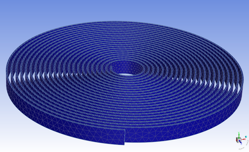
Meshing Problematic Imported CAD Geometries
Certain problematic imported CAD geometries (such as multiple coils wound around a centerpoint) may not be easily meshed using Fluent Meshing due to two uncharacteristic properties:
The ratio of the surface area and the square of the bounding box diagonal is much greater than 1.
Projecting a point located between the coils can lead to ambiguous results due to spatial proximity. This is especially problematic for surface meshing because the parameter-space-free approach is the most robust approach for the majority of models in Fluent Meshing.
To avoid issues with ambiguous point projection in such geometries, use a plane to split the face of the geometry into an upper half and a lower half:
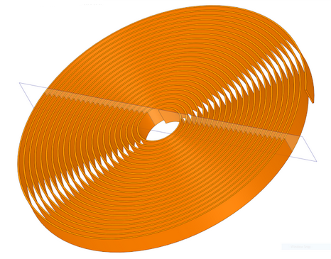
When the split model is then imported into the meshing mode of Fluent, the single volume is retained, however the face of the volume is split and you can obtain a proper mesh because the point projection ambiguity no longer exists,
Graphic window displays can be saved in various formats including: EPS, JPEG, PPM, PostScript, TIFF, PNG, HSF, GLB, and VRML. There can be slight differences between pictures and the displayed graphics windows depending on your settings and hardware, as the pictures may be generated using the internal software renderer while the graphics windows may use specialized graphics hardware for optimum performance. To eliminate such differences and save these files at the fastest rate possible, you must follow all of the following best practices:
Run Cortex on a suitable machine with an appropriate graphics card and the latest drivers (for details, see the Ansys website). Note that you can assign Cortex to a particular machine using the
-gui_machine=<hostname>command line option, or by selecting Specify Machine from the Graphics Display Machine list in the Scheduler tab of Fluent Launcher.Ensure that Cortex / the host process is run on a separate machine than that used for compute node 0. For example, do not include the machine assigned using the
-gui_machineoption as the first machine in the hosts file / machine list (specified using the-cnf=xcommand line option).Do not set the graphics driver to
null,x11(for Linux), ormsw(for Windows).When saving picture files, enable the Fast hardcopy option in the Preferences dialog box (under Graphics).
Many systems provide a utility to “dump” the contents of a graphics window into a raster file. This is generally the fastest method of generating a picture (as the scene is already rendered in the graphics window) and guarantees that the picture will be identical to the window.
For additional information, see the following sections:
You can use the Save Picture dialog box to set the parameters and to save the picture files.
For your convenience, the Save Picture dialog box can also be opened
using the button (![]() ) in the standard toolbar. The procedure for saving a picture file is
as follows:
) in the standard toolbar. The procedure for saving a picture file is
as follows:
Select the appropriate file format.
Set the coloring.
Specify the file type, if applicable (optional).
Define the resolution, if applicable (optional).
Set the appropriate options (landscape orientation, white background).
If you are generating a window dump, specify the command to be used for the dump.
Preview the result (optional).
Click the Save... button and enter the filename in the resulting Select File dialog box.
Tip: Click instead of Save... to save the current settings without saving a picture. The applied settings will become the defaults for subsequent pictures.
Choosing the File Format
To choose the file format, select one of the following options in the Format list: EPS[1][2], JPEG, PPM, PostScript[2], , TIFF[3]VRML[4], PNG, HSF, GLB, VRML, and Window Dumps (LINUX Systems).
Specifying the Color Mode
You can specify which type of Coloring you want to use for all formats except VRML and the Window Dump.
Note: Most monochrome PostScript devices will render Color images in shades of gray. Select Gray Scale to ensure that the color ramp is rendered as a linearly-increasing gray ramp.
Choosing the File Type
When you save a PostScript or EPS file, you can choose either of the following file types:
Defining the Resolution
For raster files, you can control the resolution of the image by specifying the size in pixels. Set the desired Width and Height under Resolution. If the values of Width and Height are both zero, the picture is generated at the same resolution as the active graphics window.
Note: For PostScript and EPS files, specify the resolution in dots per inch (DPI) instead of setting the width and height.
Picture Options
You can set two additional options for all picture formats except VRML and the Window Dump.
Specify Landscape Orientation (enabled, default) option, or disable for Portrait orientation.
Specify a White Background (enabled, default), or disable to use the same background as the graphics window.
Fluent also provides options that enable you to save PostScript files that can be printed more quickly. These options are available in the display/set/picture/driver/post-format text menu.
Window Dumps (LINUX Systems)
If you select the Window Dump format, the program will use the specified Window Dump Command to save the picture file. For example, if you want to use xwd to capture a window, set the Window Dump Command to
xwd -id %w >
Fluent will automatically interpret %w to be the ID number of the active window when the dump occurs.
When you click , the Select File dialog box appears. Enter the filename for the output from the window dump (for example, myfile.xwd).
To make an animation, save the window dumps into numbered files, using the
%nvariable. To do this, use the Window Dump Commandxwd -id %wand typemyfile%n.xwdas the filename in the Select File dialog box.
Note: Each time you create a new window dump, the value of %n increases by one, so you need not track numbers to the filenames manually.
If you use the ImageMagick animation program, saving the files in MIFF format (the native ImageMagick format) is more efficient. In such cases, use the ImageMagick tool import. For the Window Dump Command enter the default command:
import -window %w
Specify the output format to be MIFF by using the .miff suffix at the end of the filename.
The window-dump feature is both, system and graphics-driver-specific. The commands available for dumping windows depends on your system configuration.
Important: The window dump will capture the window exactly as it is displayed, including the resolution, colors, transparency, for example. For this reason, all of the inputs that control these characteristics are disabled in the Save Picture dialog box when you enable the Window Dump format.
Previewing the Image
Before saving a picture file, you can preview the image to be saved. Click to apply the current settings to the active graphics window so that you can see the effects of different options interactively before saving the image.
[1] (Encapsulated PostScript) output is the same as PostScript output, with the addition of Adobe Document Structuring Conventions (v2) statements. Currently, no preview bitmap is included in EPS output. Often, programs that import EPS files use the preview bitmap to display on-screen, although the actual vector PostScript information is used for printing (on a PostScript device). You can save EPS files in raster or vector format.
[2] Raster is an optional format.
[3] The TIFF driver may not be available on all platforms.
[4] VRML is a graphics interchange format that enables export of 3D geometrical entities that you can display in the graphics window. This format can commonly be used by VR systems and in particular the 3D geometry can be viewed and manipulated in a web-browser graphics window. Non-geometric entities such as text, titles, color bars, and orientation axis are not exported. In addition, most display or visibility characteristics set in Fluent, such as lighting, shading method, transparency, face and edge visibility, and outer face culling, are not explicitly exported but are controlled by the software used to view the VRML file.