


The Lagrangian Wall Film (LWF) model can be used to predict the creation and flow of thin liquid films on the surface of walls. This section presents information about the basic functionality of the LWF model.
The LWF model uses DPM particles to represent the wall-film. In the Ansys Fluent LWF model, a liquid droplet or multicomponent particle can impinge upon a boundary surface and form a thin film. The model can be broken down into four major subtopics:
interaction during the initial impact with a wall boundary
subsequent tracking on surfaces
calculation of film variables
coupling to the gas phase
All inputs and model parameters for the LWF model are specified in the DPM tab of the Wall dialog box (opened from the Boundary Conditions task page). Once you define one or more DPM injections, you will be able to select wall-film as Discrete Phase BC Type (Discrete Phase Model Boundary Conditions group box) and specify all relevant parameters in the Wall dialog box.
For additional information, see the following sections:
The Lagrangian wall film model is only available with Unsteady Particle Tracking.
The Lagrangian wall film model is not compatible with hanging node mesh refinement on walls. Though the fluid meshes can be adapted, the refined meshes must not touch walls where the wall film model is enabled.
The wall film model assumes liquid particle materials. If an inert particle interacts with a wall film boundary, it is assumed to be liquid for the wall film model calculations. For combusting particles, the wall film is applied if Wet Combustion Model is enabled and as long as the liquid fraction in the particle is nonzero. If a dry combusting particle interacts with a wall film boundary it will stick to the wall and follow the combusting particle laws.
The wall film model is not compatible with the Rosseland Radiation model.
The Workpile Algorithm option is not available with the wall film boundary condition. It will be disabled automatically when choosing to simulate a wall film on a wall.
The Eulerian Wall Film (EWF) model is not compatible with the Lagrangian wall-film boundary condition. If you want to use the EWF model in your simulation, you must first deselect wall-film as Discrete Phase BC Type in the Wall dialog box (DPM tab).
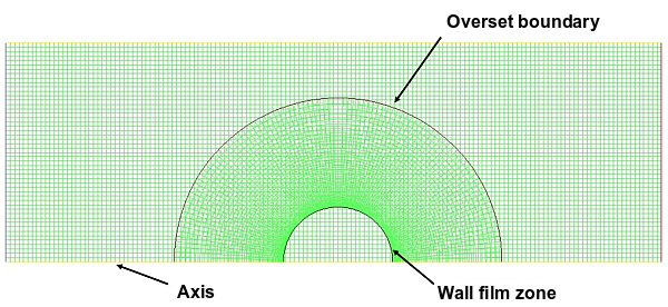
The wall film model can be used with overset meshes only if the film zone is entirely contained within a single overset mesh. Lagrangian wall film particles should not enter the overlap region of background and component meshes. An example of a valid configuration is shown in Figure 24.52: Valid Configuration for the Lagrangian Wall film Model with Overset Mesh.
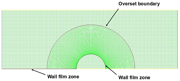
Figure 24.53: Invalid Configuration for the Lagrangian Wall film Model with Overset Mesh shows an invalid setup in which the wall film zone crosses between the background and component meshes.
For additional assumptions used by the Lagrangian wall film model, refer to Introduction and Interaction During Impact with a Boundary in the Fluent Theory Guide.
Note that the wall film model only applies when the wall-film is selected as Discrete Phase BC Type in the Wall dialog box (DPM tab). If wall film particles intersect with a boundary of another type (for example reflect), they will be released from the film and become free-stream particles. The following boundaries are exceptions:
the trap boundary condition where the wall film particles are absorbed at the wall with simultaneous release of the momentum, energy, and species (if species are defined) sources
the symmetry boundary condition where the wall film particles are reflected
Special consideration related to wall film particles defined on moving boundaries: if the particles move to another zone, where wall-film is not selected as Discrete Phase BC Type, then the particles obey the boundary condition defined for this other zone.
For the wall-film boundary condition, you can enable and/or set the following models in the DPM tab of the Wall dialog box:
Particle-Wall Heat Exchange
See Particle-Wall Impingement Heat Transfer for details about this mode.
Film condensation
See Film Condensation Model for details about this mode.
Gas-side boundary layer model (default)
See Gas-Side Boundary Layer Model for details.
Particle erosion (DPM model with the Erosion/Accretion option)
See Setting Particle Erosion and Accretion Parameters for details about modeling particle erosion.
Initialize wall film
See Patching the Wall Film for details.
Particle impingement/splashing
The following options are available in the Impingement/Splashing Model drop-down list:
stanton-rutland: (default) consists of four regimes, namely, stick, rebound, spread, and splash, which are based on the impact energy and wall temperature. See The Stanton-Rutland Model in the Fluent Theory Guide for more details.
kuhnke: consists of four regimes spread, rebound, splash, and dry splash (thermal breakup). See The Kuhnke Model in the Fluent Theory Guide for more details. You must specify the following DPM Wall Roughness Parameters:
Ra: is used to compute
 in Equation 12–249 in the Fluent Theory Guide.
Rz: is used to compute splashed droplets ejection angle in Equation 12–261 in the Fluent Theory Guide.
stochastic kuhnke: is derived from the Kuhnke model and has been developed and tuned for addressing Selective Catalytic Reduction (SCR) modeling applications. It introduces stochastic effects into the critical temperature transition process, and the “partial evaporation” concept for the evaporative splash regime. See The Stochastic Kuhnke Model in the Fluent Theory Guide for details. For this model you must specify Rz under the DPM Wall Roughness Parameters. This parameter will be used to interpolate the constant
 from Parameter A as a Function of Wall Roughness in the Fluent Theory Guide,
which will be subsequently used in Equation 12–267 in the Fluent Theory Guide to calculate critical Weber number for splashing on a dry
wall.
from Parameter A as a Function of Wall Roughness in the Fluent Theory Guide,
which will be subsequently used in Equation 12–267 in the Fluent Theory Guide to calculate critical Weber number for splashing on a dry
wall.
If you want to model splashing, specify Number of Splash Drops (in the Impingement/Splashing Parameters group box). A value of zero implies that the splashing model will not be used.
Regime parameters
When modeling drop/wall impingement/splashing using the stanton-rutland and kuhnke models, you can calculate the critical transition temperature (
 ) of the fluid that forms the film via one of the following options in the
Regime Parameters group box:
) of the fluid that forms the film via one of the following options in the
Regime Parameters group box:critical temperature factor: uses Equation 12–210 and Equation 12–240 in the Fluent Theory Guide for the stanton-rutland and kuhnke splashing models, respectively
calibratable temperature: uses Equation 12–211 and Equation 12–241 in the Fluent Theory Guide for the stanton-rutland and kuhnke models, respectively
The calibratable temperature may improve the predictions for Selective Catalytic Reduction (SCR) systems.
When modeling drop/wall impingement/splashing using the stochastic kuhnke model, specify the following parameters in the Regime Parameters group box:
Upper Deposition Limit Offset: is
 in Equation 12–264 in the Fluent Theory Guide
Deposition Delta T: is
 in Equation 12–265 in the Fluent Theory Guide
Laplace Number Constant: is
 in Equation 12–266 in the Fluent Theory Guide
Partial Evaporation Ratio: is the mass fraction of the impinging liquid spray that vaporizes immediately upon impact when the droplet is in the evaporative splash regime
Film stripping
To model film stripping, enable Particle Stripping and specify Critical Shear Stress (Stripping Model Parameters group box). When this value is exceeded, mass will be taken from the film on the face where liquid film exists.
Optionally, you can use the following text user interface commands to specify:
diameter coefficient (
 in Equation 17–20 in the Theory Guide):
define/models/dpm/stripping-options/diameter-coefficientmass coefficient (
 in Equation 17–21 in the Theory Guide):
define/models/dpm/stripping-options/mass-coefficient
Important: Particle stripping can be modeled only if the film contains a single particle material or a single particle-mixture material. The combusting-particle type is not supported.
For theoretical information about this option, see Film Stripping in the Fluent Theory Guide.
Film separation
You can select from the following options from the Film Separation Model drop-down list (in the Separation Model Parameters group box):
o'rourke
foucart (3d only)
friedrich.
Details about these models can be found in Separation Criteria in the Fluent Theory Guide.
You can also specify:
Critical Weber Number: is
 in Equation 17–7 in the Fluent Theory Guide
Film Separation Angle: is θcritical in Equation 17–7 in the Fluent Theory Guide
Note: Selecting wall-film automatically enables the Consider Children in the Same Tracking Step option in the Discrete Phase Model dialog box (Physical Models tab).
Additional modeling options available via the Text User Interface (TUI) are described in the following sections:
The default heat transfer model assumes that the heat is transferred from the wall to the film by conduction only. If you want to include convective heat transfer, issue the following text command:
define/models/dpm/options/convective-film-heat-transfer?
and enter yes at the prompt:
Enable convection/conduction film to wall heat transfer (else conduction only)? [no]yes
By default, the convective heat transfer model uses the turbulent approximation described
in Convective Heat Transfer Model in the Fluent Theory Guide. To
disable it, enter no at the next prompt:
Enable turbulent film heat transfer approximation? [yes]no
This model is recommended for thicker films, films with high velocity, and films of high Prandtl number liquids. In addition, films formed by jet impingement will be represented more accurately with this model since it includes a formulation that specifically takes into account liquid jet impingement processes.
Note: When enabling the convective wall-film heat transfer model for older Ansys Fluent cases with film particles already existing on the wall, a modified and less accurate formulation will be applied. The current model implementation requires the distance of the film particle from the impingement location to be known. This information is not available for existing film particles. Therefore, if you want to use the convective wall-film heat transfer model for wall-film calculations in older Ansys Fluent cases, it is recommended that you clear existing film particles and recalculate the film.
See Convective Heat Transfer Model in the Fluent Theory Guide for more information about the convective wall-film heat transfer model.
In Ansys Fluent, the wall temperature is limited by default. The limit is calculated by Equation 12–205 in the Fluent Theory Guide. You can remove the wall temperature limit by invoking the following text command:
define/models/dpm/options/remove-wall-film-temperature-limiter?You will be asked:
Remove the wall film temperature limiter [no]:If you answer yes, the wall temperature will not be limited during
the simulation, resulting in a smoother wall film appearance. However, it may introduce
instabilities to the film formation process, and may have the effect that the wall film
completely evaporates off the wall.
If you answer no (recommended), you will be prompted to define the
temperature difference above the Boiling point:
Temperature difference above the liquid film boiling point [50]:You will be then prompted whether you want to enable the reporting of the Leidenfrost temperature on the wall faces:
Report the Leidenfrost temperature on wall film faces [yes]Answering yes makes the Leidenfrost
Temperature variable available for postprocessing. For the DPM verbosity level
higher than 1 (set by the text command
define/models/dpm/numerics/verbosity), Ansys Fluent reports in the
console for every DPM iteration the percent of the wall area covered by film and percent of
film mass where the wall temperature is above the Leidenfrost point.
For more information, see Leidenfrost Temperature Reporting in the Fluent Theory Guide.
Detailed information on the wall film model can be found in Lagrangian Wall-Film Model Theory in the Fluent Theory Guide.
For a list of limitations that exist with wall-film boundary conditions, see Limitations on Using the Lagrangian Wall Film Model.
Condensation can be defined as the transition from the gas phase to the liquid phase as a
vapor condenses on a surface. The Ansys Fluent film condensation model is triggered when the partial
pressure of vapor species  in the bulk gas mixture exceeds either its vapor pressure at the wall-film or,
in case no film exists, at the wall temperature. When these conditions are met, the vapor
species will condense and form the liquid film on the wall faces.
in the bulk gas mixture exceeds either its vapor pressure at the wall-film or,
in case no film exists, at the wall temperature. When these conditions are met, the vapor
species will condense and form the liquid film on the wall faces.
The following limitations currently exist in the film condensation model:
The film particles are stagnant
Only particles of a single material (droplet or multicomponent) can condense on a particular wall face
At least one species in the gas phase mixture must be non-condensable
To use the film condensation model:
Enable the following models:
Energy equation
Species Transport model
Unsteady Particle Tracking (in the Discrete Phase Model dialog box)
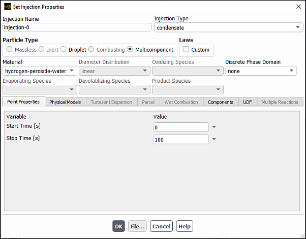
If no droplet or multicomponent injection exists in the DPM case setup, create a condensate injection by selecting condensate from the Injection Type dropdown list in the Set Injection Properties dialog box and define the injection properties as appropriate.
Note: A droplet or multicomponent injection must exist to define the vapor–liquid material pair for the condensation process.
For further information, see Injection Types, Point Properties for Condensate Injections, and Defining Injection Properties.
For each droplet and multicomponent injection, specify the condensable species by selecting the Evaporating Species.
In the Wall dialog box, under the DPM tab, select wall-film from the Discrete Phase BC Type drop-down list and enable the Film Condensation option for each wall where condensation may occur. If the Gas-Side Boundary Layer Model option is disabled, the Fluent solver automatically enables it. For more information, see Gas-Side Boundary Layer Model.
Note: Film Condensation is available only with the wall-film DPM boundary condition.
Enable Linearized Source Terms in the Numerics tab of the Discrete Phase Model dialog box.
Enabling the Linearized Source Terms option helps to stabilize the condensation solution and is strongly advisable.
When the appropriate conditions exist, the evaporating species you have selected will condense on the walls that have the Film Condensation option enabled forming either droplet or multicomponent film particles (depending on the Particle Type selected in the Set Injection Properties dialog box).
For information about the theory behind the Film Condensation model, see Film Condensation in the Fluent Theory Guide.
The Gas-Side Boundary Layer model enables the boundary layer formulations for the mass and heat transfer equations for film vaporization and boiling as described in Film Vaporization and Boiling and Energy Transfer from the Film in the Fluent Theory Guide.
The model is enabled by default. To disable it, clear Gas-Side Boundary Layer Model in the DPM tab of the Wall dialog box (Discrete Phase Model Boundary Conditions group box). Note that the boundary layer formulations are always used for both condensation and vaporization rates when the Film Condensation model is enabled.
When a DPM case with the wall-film boundary condition is initialized or data is read, you can initialize the Lagrangian wall film (LWF) as follows:
In the DPM tab of the Wall dialog box, enable Initialize Wall Film (Discrete Phase Model Boundary Conditions group box).
Once Initialize Wall Film is selected, you can specify the following parameters in the Wall Film Initial Conditions group box:
- Film Height
is the prescribed height of the film. When the film height is prescribed the film mass can be computed by the following equation:
where
 = prescribed film height (m)
 = wall face area (m2)
 = particle density assigned from the injection selected (kg/
m3)
= particle density assigned from the injection selected (kg/
m3)- Film X, Y, Z Velocity
are the X, Y, and Z (for 3D flows) components of the film initial velocity that are assigned directly to the film parcels.
- Film Temperature
is the initial temperature of the film. This input is available only if Energy is enabled.
- Minimum Number Of Parcels Per Face
is the minimum number of film parcels that are assigned per face. Note that for highly non-uniform meshes, a value of 1 is recommended.
- Minimum Film Parcel Surface Density
is the minimum surface density of the film parcels. This value will be overridden if the number calculated from Minimum Number Of Parcels Per Face is larger than the number entered here. For example, if the Minimum Number Of Parcels Per Face is specified as 10, and the Minimum Film Parcel Surface Density is specified as 1,000,000/m2, then this value will be overridden for any wall face with a surface area less than 1e-5 m2. So, if a wall face surface area = 9e-6 m2, then:
Because the resulting value is less than 10, the number of parcels assigned to this wall face will be 10.
If the wall face surface area = 1.1e-5 m2, then:
and the number of parcels assigned to this wall face will be 11.
- Initialize From Injection
is used to assign the injection material and the corresponding physical properties to the film.
Click .
All the settings in Wall dialog box will be applied, and the Lagrangian wall film on the selected wall zone will be initialized immediately.


Ansys Fluent uses a random number sequence to distribute the parcels on each of the wall faces with the following exception: when one single parcel is assigned to a face, the parcel is placed on the face centroid.
Also, you can reset the LWF to zero from the Solution Initialization task page by clicking Reset LWF. This will delete the LWF film particles as well as zero out the corresponding face variables without affecting the free stream particles.
In addition, by clicking in the Solution Initialization task, you can initialize (or patch) the Lagrangian wall film on all wall zones for which the wall-film boundary condition has been chosen and Initialize Wall Film has been selected.