


The Eulerian wall film model can interact with the discrete phase model (DPM), VOF multiphase model, and Eulerian multiphase model through source terms to the film equations. During the interaction with the DPM model, the discrete particles are collected to form a wall film. The discrete particles can splash when interacting with a film boundary, creating additional particles in the same way as described in the Lagrangian film model. Additional particles can be created when the film separates from the wall, or when the shear stress is sufficient that large particles can be stripped from the film. Mass leaving the film surface by separation or stripping is accounted for through source terms to the film equations. In the Eulerian multiphase interaction, a secondary phase in the multiphase flow is captured on solid surfaces, forming liquid films. Collection efficiency can be computed for the solid surfaces. Mass and momentum leaving the liquid film due to separation and stripping is added to the secondary phase in the multiphase flow. In the interaction with the VOF multiphase model, film liquid excess of a specified limit can be modeled using the VOF model, and a secondary phase fluid in a VOF multiphase flow with small volumes below a specified limit can modeled using the wall film model.
Discrete particle streams or discrete particles hitting a face on a wall boundary are absorbed into the film. When particles are absorbed, their mass and momentum are added to the source terms in Equation 17–1 and Equation 17–2, continuity and momentum equations, respectively. The mass source term is given by
 | (17–4) |
where  is the flow
rate of the particle stream impinging on the face. The momentum source
term is
is the flow
rate of the particle stream impinging on the face. The momentum source
term is
 | (17–5) |
where  denotes the
velocity of the particle stream and
denotes the
velocity of the particle stream and  denotes the film velocity.
Impingement of particles on the film wall boundary may result in particle rebounding, splashing or being absorbed to form wall film. Details of the particle interaction with the wall boundary is described in the Lagrangian film model (Interaction During Impact with a Boundary).
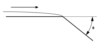
The film can separate from an edge if two criteria are met – first that the angle between faces is sufficiently large and second if the film inertia is above a critical value (defined by you). If separation occurs, a source term in the film equation is used to remove mass and momentum from the face corresponding to the edge upstream of where the separation occurs. This source term is accumulated at each film time step, and particle streams are created at DPM iterations using this source. New particle streams are created only during the DPM iteration, however the source terms due to film separating from an edge are updated each film step.
Based on the work by Foucart, separation can occur at an edge if a critical angle,
θcritical, is exceeded and a Weber number based on the
film,  , is above a minimum value.
The Weber number is defined as,
 | (17–6) |
and  is surface tension of the film. The separation criteria
become,
is surface tension of the film. The separation criteria
become,
 | (17–7) |
Once separation occurs, you can specify three different models to calculate the number and diameter of the shed particle stream at an edge, based on work by Foucart ([188]), O’Rourke ([495]) and Friedrich ([193]).
The Foucart model for edge separation assumes that the drop diameter is given by
 | (17–8) |
where  is the length of the edge and
  the height of the film. The flow
rate
the height of the film. The flow
rate  of the particles from the film is equal to the mass
flux of the film across the edge
of the particles from the film is equal to the mass
flux of the film across the edge
 | (17–9) |
where  is the inward pointing normal from the edge centroid
to the face center. The particles separated from an edge using Foucart’s
criterion are given the velocity of the film at the edge where the
separation occurs.
is the inward pointing normal from the edge centroid
to the face center. The particles separated from an edge using Foucart’s
criterion are given the velocity of the film at the edge where the
separation occurs.
The O’Rourke model for edge separation assumes that the drop diameter is equal to the height of the film at the edge, and the flow rate of the particles from the film is equal to the mass flux of the film across the edge.
Friedrich’s separation model assumes that the drop diameter is equal to the height of the film at the edge, but the flow rate of the particles from the film is calculated from an experimentally derived force ratio between the inertia of the film and the surface tension forces.
The force ratio is given by
 | (17–10) |
where  and the characteristic breakup
length
and the characteristic breakup
length  is given by:
 | (17–11) |
and the relative Weber number  and the film flow Reynolds number are defined as
follows,
and the film flow Reynolds number are defined as
follows,
 | (17–12) |
 | (17–13) |
Unlike the O’Rourke or Foucart separation methods, the mass flux into the particle stream is an experimentally derived percentage of the flux across the edge as given in Equation 17–9. This percentage is assumed to be a function of the force ratio given by:
 | (17–14) |
which is a curve fit to the data in Friedrich, et.al. ([193]) and is valid for force ratios greater than one (that is, separated flows). If the force ratio in the Friedrich correlation is less than one, no separation takes place.
Film stripping occurs when high relative velocities exist between the gas phase and the liquid film on a wall surface. At sufficiently high shear rates, Kelvin-Helmholtz waves form on the surface of the film and grow, eventually stripping off droplets from the surface. The model for this behavior in the current implementation of the wall film model in Ansys Fluent is based on work by Lopez de Bertodano, et al. ([390]) and Mayer ([417]).
As described in Mayer, in a thin liquid sheet in a shear flow, waves of length λ are formed due a Kelvin-Helmholtz type of instability, but the waves are damped out by viscous forces in the film. The balance of wave growth and damping provides a term for the frequency ω
 | (17–15) |
where
 | (17–16) |
with  as a sheltering parameter with a value of 0.3, and
 | (17–17) |
In Equation 17–16,  is the gas velocity.
For waves to grow and eventually break off from the film, ω must be greater than zero which implies that the minimum wave length for growing waves should be:
 | (17–18) |
An expression for frequency from Taylor's theory can be derived using linear stability analysis, and is given by Lopez de Bertodano et al [390]
 | (17–19) |
Following Mayer, the average droplet size of the stripped droplets is
 | (17–20) |
where  (with a default value of 0.14) is a numerical factor
that is equivalent to the in the graphical user interface.
(with a default value of 0.14) is a numerical factor
that is equivalent to the in the graphical user interface.
To obtain a mass flow rate at the surface of the liquid, it
is assumed that  where
where  is the average wavelength of the disturbance. Mayer
uses the expression
is the average wavelength of the disturbance. Mayer
uses the expression  which results in the following expression
for the flow rate of drops stripped from the surface:
which results in the following expression
for the flow rate of drops stripped from the surface:
 | (17–21) |
where  (with a default value of 0.5)
is a numerical factor that is equivalent to the in the graphical user interface. Mass sources are accumulated during
the course of the film calculation according to the above expression,
and are injected into the free stream with the velocity of the film
and the calculated mass flow rate from the face during the DPM iteration.
(with a default value of 0.5)
is a numerical factor that is equivalent to the in the graphical user interface. Mass sources are accumulated during
the course of the film calculation according to the above expression,
and are injected into the free stream with the velocity of the film
and the calculated mass flow rate from the face during the DPM iteration.
No mass will be taken from the film unless the critical shear stress (defined in the graphical user interface) is exceeded on the face where liquid film exists.
In an Eulerian multiphase flow, the secondary phase to be collected on a solid surface must have the same material as defined in the Eulerian wall film model. When the secondary phase is captured by the wall surface, its mass and momentum are removed from the multiphase flow, and added as source terms to the continuity and momentum equations, Equation 17–1 and Equation 17–2 respectively, of the wall film.
The mass source term is given by
 | (17–22) |
where  is the secondary phase volume fraction,
  is the secondary phase density,
  is the phase
velocity normal to the wall surface, and
is the phase
velocity normal to the wall surface, and  is the wall
surface area.
is the wall
surface area.
The momentum source is give by
 | (17–23) |
where  is the secondary
phase velocity vector.
is the secondary
phase velocity vector.
The collection efficiency of the secondary phase is computed as
 | (17–24) |
where  and
and  are the reference (far field) secondary phase concentration and
velocity, respectively.
are the reference (far field) secondary phase concentration and
velocity, respectively.
The Eulerian wall film model can also be coupled with the mixture species transport model to consider phase changes between film material (liquid) and the gas species (vapor). The phase change rate is modeled using following models:
Diffusion Balance Model
The rate of phase change is governed by

(17–25)
where
 is the density of the gas mixture,
 is the mass diffusivity of the vapor
species,
is the mass diffusivity of the vapor
species,  is the cell-center-to-wall distance,
 is the phase change constant, and
 represents the cell-center mass fraction
of the vapor species. The saturation species mass fraction
is computed as
represents the cell-center mass fraction
of the vapor species. The saturation species mass fraction
is computed as
(17–26)
where
 is the absolute pressure of the gas
mixture and,
is the absolute pressure of the gas
mixture and,  and
and  is the molecular weight of the vapor
species and the mixture, respectively. The saturation
pressure
is the molecular weight of the vapor
species and the mixture, respectively. The saturation
pressure  is a function of temperature only. By
default, water vapor is assumed to be the vapor species
and its saturation pressure is computed, following
Springer et al ([626]), as
is a function of temperature only. By
default, water vapor is assumed to be the vapor species
and its saturation pressure is computed, following
Springer et al ([626]), as
(17–27)
However, you can replace the above default formulation by using a user-defined property when defining the vapor material in the Materials task page.
It is clear from Equation 17–25 that when the vapor mass fraction exceeds the saturation mass fraction, condensation takes place (that is, negative
 ) instead, when the vapor mass fraction
is less than the saturation mass fraction, the liquid film
vaporizes. The phase change constant in Equation 17–25 takes
different values for condensation and vaporization,
respectively.
) instead, when the vapor mass fraction
is less than the saturation mass fraction, the liquid film
vaporizes. The phase change constant in Equation 17–25 takes
different values for condensation and vaporization,
respectively. 
(17–28)
where the film height
 is used to prevent generating vapor
without the presence of liquid.
is used to prevent generating vapor
without the presence of liquid.Wall Boundary Layer Model
Details about the Wall Boundary Layer model are provided in Mass Transfer from the Film.
User Defined Model
User-defined phase change rates can be specified through user-defined profile UDFs. Note that such UDFs must return the relevant rates as positive values in kg/s. The UDF returned rate will be converted into kg/s/m2 with appropriate signs internally in the code.
When the liquid film accumulation becomes prominent, and the film thickness exceeds a specified maximum limit, the EWF model may not yield valid computational results. The ability to connect the EWF and VOF multiphase models enables the transition of the film liquid solution between the two models such that the solution of the accumulated film liquid can be carried out by the VOF multiphase model. Moreover, in VOF modeling, there are situations where the volume of fluid near a wall boundary can become very small. Resolving such small fluid volumes using the VOF model can be impractical and expensive. In such cases, a VOF to wall film transition allows the small volumes of fluid to be modeled using the EWF model.
Ansys Fluent provides the capability to couple the EWF and VOF multiphase models allowing a hybrid solution approach for such cases.
During an EWF and VOF model transition, mass, momentum and energy terms of the film and the secondary phase liquid are transferred between the two models. The transition can be based on one of the two transition bases:
A transition based on the volume fraction uses the film or secondary phase liquid volume fraction in the computation cells next to film walls
A transition based on the height fraction uses the ratio of either the film or the equivalent film half height to the cell center distance to film walls.
With both transition bases, a weighted film height threshold is computed from the specified transition criterion and used to determine the onset of a transition.