An M120 structural steel bolt with standard thread dimensions is modeled with a cover plate and a base plate of reasonable dimensions. Both 2D and 3D bolt thread modeling is performed. A bilinear isotropic plastic material model is used for the bolt and the plates.
Modeling of this problem is done through the following steps:
Two models, one with a threaded bolt surface and another with a smooth bolt surface, are created to demonstrate the simplicity and advantage of the bolt section method over the true thread simulation method.
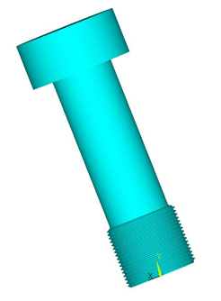
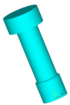
The 3D threaded bolt model represents a single start M120 bolt with a cover plate and a base plate. The bolt has a maximum diameter of 120 mm, a pitch diameter of 116 mm, a 6 mm pitch, and a half thread angle of 30 degrees (according to the standard thread profile).
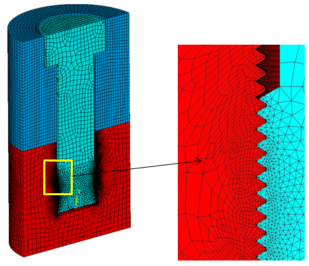
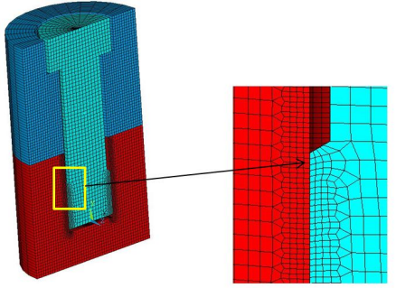
The model is meshed with SOLID186 and SOLID187 elements. Mesh refinement is performed in the thread region.
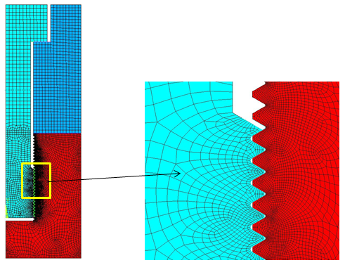
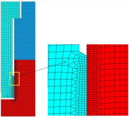
The 2D surface geometry is extracted from the 3D thread geometry. The 2D model is meshed with PLANE183 axisymmetric elements (KEYOPT(3) = 1).
Instead of modeling a true threaded bolt, smooth cylindrical surfaces are created for both the bolt and base plate.
A 2D axisymmetric model is created and meshed with PLANE183 axisymmetric elements (KEYOPT(3) = 1).
The 3D model is generated with SOLID186 elements by extruding the 2D axisymmetric model about the Y-axis with the EEXTRUDE command.
eextrude,,30,,,360 !creates 3D model by rotating 2D axisymmetric model about y-axis
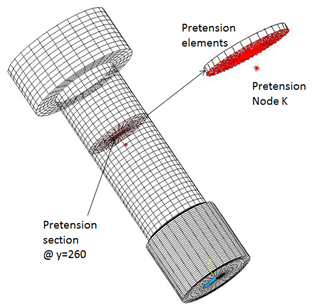
Pretension is the most important aspect of the simulation of the bolted structure. It transfers the load in the model while sustaining only a small part of the external load on the bolt. The preload on the bolt is caused by the tightening of the bolt to fasten the cover plate to the base plate. Pretension in the bolt is modeled by cutting the bolt into two segments and pulling each segment toward the other.
The following steps and commands illustrate the procedure to simulate pretension in the bolt:
Mesh the bolt, then cut the mesh and insert PRETS179 elements to form the pretension section. The PSMESH command is used to create pretension elements in the bolt at y = 260 mm.
ESEL,S,TYPE,,<type number>			!selection of bolt elements by element type number
PSMESH,,,,ALL,,,y,260,,,,ECOMP,NCOMP	  !automatically generate the pretension elements @ y = 260
The SLOAD command is used to apply the pretension load. In the first load step, the pretension load is applied as a force to node K. In the second load step the force locks, allowing additional loads. The effect of the initial load is preserved as a displacement after it is locked.
SLOAD,1,PL01,lock,FORC,2544690,1,2
Three frictional contact pairs are defined to simulate the contact interfaces in the model. The coefficient of friction in the contact region is 0.15. Contact regions are meshed with CONTA174 elements for the 3D case and with CONTA172 elements for the 2D axisymmetric case. The augmented Lagrange algorithm is used (KEYOPT(2) = 0). Target surfaces are meshed with TARGE170 elements for the 3D case and TARGE169 elements for the 2D axisymmetric case.
Contact pairs are modeled in the following regions:
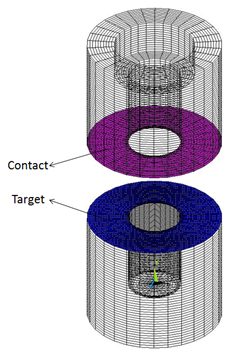
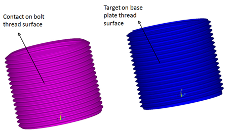
A surface-to-surface contact pair is defined between the bolt and the base plate. Contact in the thread region is modeled differently for each of the three simulation methods.
A frictional contact pair is defined between the bolt thread surface (the contact surface) and the base plate thread surface (target surface). The surface projection contact detection method (KEYOPT(4) = 3) is used because it provides more accurate contact tractions and stresses for underlying elements compared with other contact detection methods.
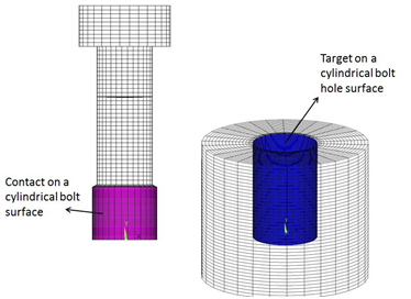
Contact elements (CONTA174 for the 3D case, CONTA172 for the 2D case) are generated on the smooth cylindrical bolt surface. A bolt section is assigned to the contact elements to simulate the thread. The contact region is computed internally based on the user-specified thread geometry data and the two end points of the bolt axis. Target elements (TARGE170 for the 3D case, TARGE169 for the 2D case) are overlaid on the smooth cylindrical hole of the base plate.
The SECTYPE and SECDATA section commands are used to define the bolt section for contact elements. The format for these commands is shown below.
SECTYPE,SECID,CONTACT,BOLT
SECDATA,Dm,P,ALPHA,N,X1,Y1,Z1,X2,Y2,Z2
| where |
Dm = Pitch
diameter, dm |
P = Pitch distance, p |
ALPHA = Half-thread angle, α |
N = Number of starts (defaults to
1) |
X1, Y1,
Z1, X2,
Y2, Z2 = Two
end points of the bolt axis in global Cartesian coordinates |
The following commands illustrate the procedure for bolt thread modeling using the bolt section commands:
et,100,174                ! Define contact element type
keyopt,100,4,3            ! Define surface projection based contact detection method
keyopt,100,10,2           ! Update stiffness at each iteration
mp,mu,100,.15             ! Frictional co-efficient
sectype,5,contact,bolt
secdata,116,6,30,,0,0,0,0,162,0
et,101,170                ! Define target element type
r,100,
cmsel,s,bolt_thread,node
type,100
mat,100
real,100
secn,5                     ! Assign the section to contact elements
esurf
cmsel,s,bottomplate_thread,node
type,101
mat,100
real,100
secn,0
esurf
allsel,all
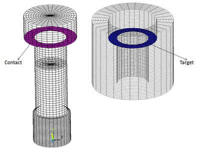
In this method, MPC bonded contact behavior is defined between the smooth cylindrical bolt surface and the smooth base plate. There is no thread behavior defined. To define MPC contact, the following contact elements KEYOPT settings are used:
| KEYOPT(2) = 2 - MPC algorithm |
| KEYOPT(4) = 2 - Nodal contact detection |
| KEYOPT(12) = 5 - Always bonded behavior |
A frictional contact pair is defined between the bolt head (the contact surface) and the cover plate (the target surface). The surface projection contact detection method (KEYOPT(4) = 3) is used for this contact pair.
A frictional contact pair is defined between the cover plate (the contact surface) and the base plate (the target surface). The surface projection contact detection method (KEYOPT(4) = 3) is used for this contact pair.