


Preloads in bolts and other structural components often have significant effect on deflections and stresses. Two features, the PRETS179 pretension element and the PSMESH pretension meshing command, can be used for this type of analysis. If the fastener has been meshed in two separate pieces, the pretension elements can be inserted between the pieces using the EINTF command.
The pretension load is used to model a pre-assembly load in a joint fastener. The pre-load ensures that the mating parts stay connected during the operation of the machine. The working load acting on the bolt is distributed across the assembly.
Warning: Negative pretension load may cause bolt loosening and allow rigid body motion. If you apply negative pre-load, the working load will not be distributed across the assembly.
The fastener can be made up of any 2D or 3D structural, low- or high-order solid, beam, shell, pipe, or link elements. When using the PSMESH command, the pretension section, across which the pretension load is applied, must be defined inside the fastener.
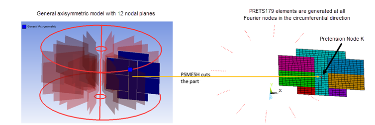
The pretension section is also applicable to fastener models meshed with general axisymmetric elements (SOLID272 and SOLID273). In this case, PSMESH cuts the model and generates PRETS179 elements between all Fourier nodes in the circumferential direction.
The easiest way to apply pretension elements to a fastener is via the PSMESH command. You can issue the command only if the fastener is not meshed in separate pieces. The command defines the pretension section and generates the pretension elements. It automatically cuts the meshed fastener into two parts and inserts the pretension elements. If you want to remove the pretension elements, you can do so automatically by deleting the pretension section. This feature also enables you to undo the cutting operation by merging nodes.
The normal direction is specified via the PSMESH command and is part of the section data.
The meshed pretension section does not need to be flat. The elements underlying the pretension section can have almost any shape: line, triangle, quadrilateral, tetrahedron, wedge, or hexahedron; however, there must be coincident nodes on the two sides (A and B) of the pretension section. Sides A and B on the pretension section are connected by one or more pretension elements, one for each coincident node pair.
Pretension node K is for controlling and monitoring the total tension loads. The pretension load direction of the pretension section can be specified relative to side A when the section is created. All pretension elements on a specific pretension section must use the same section, and must have the same pretension node K. Node K is the third position for the pretension element definition.
If the fastener has been meshed in two separate pieces, the pretension elements
(PRETS179) can be inserted between the pieces via
EINTF,TOLER,K.
If K is not defined, the program creates it
automatically.
You must define the element type ID and section properties before issuing the EINTF command. (See the SECDATA command for more information about using the PRETENSION section type.)
The connecting surfaces (A and B) must have matching mesh patterns with coincident nodes. If some node pairs between the two surfaces are not connected with pretension elements, the resulting analysis can be inaccurate.
The following example describes the typical procedure used to perform a pretension analysis using the PSMESH command.
Mesh the bolt joint, then cut the mesh and insert the pretension elements to form the pretension section. For example, the following creates a pretension section called "example" by cutting the mesh and inserting the section into volume 1. A component is created as well (npts) that aids in plotting or selecting the pretension elements.
psmesh,,example,,volu,1,0,z,0.5,,,,npts
In the first load step, apply a force or displacement to node K. In this case, the load is applied as a force. The force "locks" on the second load step, allowing you to add additional loads. The effect of the initial load is preserved as a displacement after it is locked. This is shown in the following example.
sload,1,PL01,tiny,forc,100,1,2
Apply other external loads as required using the SLOAD command.

The model represents a 180° slice of two annular plates and a single bolt assembled with an offset. The bolt is carbon steel, and the plates are aluminum. (See Figure 3.23: Initial Meshed Structure.)

Use the PSMESH operation to separate the elements of the bolt into two unconnected groups, tied together with PRETS179 pretension elements. We then plot the element and node components on the pretension interface. (See Figure 3.24: Pretension Section.)

Apply constraints for symmetry and to prevent rigid body motion. The uniform temperature defaults to the reference temperature of 70°F. Apply half of the load (as this is a half model) to the pretension node created by PSMESH, solve, and plot the normal stress in the axial direction. As expected, the axial stress is tensile in the bolt, and compressive in the portion of the plates compressed by the bolt heads. (See Figure 3.25: Pretension Stress.)
/prep7
et,1,187
mp,ex,1,1e7
mp,alpx,1,1.3e-5
mp,prxy,1,0.30
mp,ex,2,3e7
mp,alpx,2,8.4e-6
mp,prxy,2,0.30
tref,70

/foc,,-.09,.34,.42
/dist,,.99
/ang,,-55.8
/view,,.39,-.87,.31
/pnum,volu,1
/num,1
cylind,0.5,,  -0.25,0,  0,180
cylind,0.5,,  1,1.25,   0,180
cylind,0.25,, 0,1,      0,180
wpoff,.05
cylind,0.35,1, 0,0.75, 0,180
wpoff,-.1
cylind,0.35,1, 0.75,1, 0,180
wpstyle,,,,,,,,0
vglue,all
numc,all
vplot
mat,1
smrt,off
vmesh,4,5
mat,2
vmesh,1,3
/pnum,mat,1
eplot
psmesh,,example,,volu,1,0,z,0.5,,,,elems
cm,lines,LINE
/dist,,1.1
cmplot
/solu
eqslve,pcg,1e-8
asel,s,loc,y
da,all,symm
asel,all
dk,1,ux
dk,12,ux
dk,1,uz
rescontrol,linear,all,1
sload,1,PL01,tiny,forc,100,1,2
/title,Sample application of PSMESH - preload only
solve
!!!!!!!!!!!!!!!!!!!!!!!!!!!!!!!!!!!!!!!!!!!!!!!!!!!!!!!!!!!!!
! Finally, we construct the actual solution of interest. We want to
! know what happens to the preload in the bolt, and the stress field around
! it, when the assembly temperature rises to 150 degrees F.
! Both the preload and the stresses increase because, for a uniform
! temperature rise, there is greater thermal expansion in the aluminum plates
! than in the steel bolt. Any method for applying preload that did not
! allow the load to change would be unable to predict this result.
!!!!!!!!!!!!!!!!!!!!!!!!!!!!!!!!!!!!!!!!!!!!!!!!!!!!!!!!!!!!!
/post1
/show,JPEG
plnsol,s,z
prnsol,s,COMP
/show,CLOSE
/solu
antype,,restart
tunif,150
/title,Sample application of PSMESH - uniform 150 degrees
solve
/post1
/show,JPEG
plnsol,s,z
prnsol,s,COMP
/show,CLOSE
/com,*                 CHECK HERE                        *