The previous example of a simplified gear teeth multistage system (Linear Perturbation Harmonic Response Analysis of Two Stages) is used here to show how to perform a linear perturbation mode superposition (MSUP) harmonic response analysis. Specifically, it demonstrates the following key points:
Performing a linear perturbation MSUP harmonic response analysis.
Applying loading to 2 stages.
Applying an engine order load using a table having MSHI as a variable to automatically copy loads to the duplicate sectors (see Harmonic Index-based Tabular Loads).
Postprocessing any sector results in /POST26.
The example problem is presented in the following sections:
The multistage system is comprised of two axially aligned cyclic stages representing gears with, respectively, 24 and 45 teeth around their circumference as depicted in Figure 7.30: Multistage Model with Two Gear Teeth Stages.
For the base step of the linear perturbation (LP) multistage analysis, both HI = 0 stages undergo a rotational velocity and a temperature load. Both stages are then subjected to an engine order 2 excitation modeled using a single harmonic index (HI = 2) in an LP modal analysis of the system. Two engine order load vectors (one for each stage) are created in a modal restart step. The load vectors are applied using the LVSCALE command during the MSUP harmonic step.
A standard MSUP expansion pass is performed to recover the harmonic results on base and duplicate sectors. Full 360° /POST1 results are obtained by multistage cyclic expansion (MSOPT,EXPA). Frequency response plots on any sector are obtained by manually combining results on base and duplicate sectors in /POST26.
The following table describes the key steps and related commands used for the example analysis. See Input for the Analysis for the detailed command listing.
| Step | Description | Mechanical APDL commands |
| 1. | Read in stage meshes for base and duplicate sectors. | CDREAD,… |
| 2. | Duplicate meshes. | DUPLSTG.mac (macro provided) |
| 3. | Create stage components. | CM,... |
| 4. | Create HI = 0 stages and apply cyclic constraints. |
MSOPT,NEW,,,0 |
| 5. | Apply interstage constraints for all stage connections. | CEIMS,… |
| 6. | Enter the solution processor. | /SOLU |
| 7. | Specify static analysis options. |
ANTYPE,STATIC |
| 8. | Apply rotational load. | OMEGA,… |
| 9. | Specify temperature load. | TREF,… BF,,TEMP |
| 10. | Apply boundary conditions | D,… |
| 11. | Solve the analysis. | SOLVE |
| 12. | Exit and reenter the solution processor. | |
| 13. | Perform static LP restart and reform matrices for harmonic response |
ANTYPE,STATIC,RESTART,,,PERTURB PERTURB,MODAL SOLVE,ELFORM |
| 14. | Specify modal analysis options. |
MODOPT, … MXPAND,… |
| 15. | Modify used stages and delete unused stage clones. |
MSOPT,MODIFY |
| 16. | Apply interstage constraints for desired stages and stage clones. | CEIMS |
| 17. | Solve the analysis. | SOLVE |
| 18. | Exit and reenter the solution processor. | FINISH |
| 19. | Restart modal analysis to define load vectors to be used in the downstream harmonic analysis |
ANTYPE,MODAL,RESTART SF,… SFE… |
| 20. | Solve the analysis. | SOLVE |
| 21. | Exit and reenter the solution processor. | FINISH |
| 22. | Specify harmonic response options. |
HROPT,MSUP HARFRQ,… NSUBST,… |
| 23. | Apply nodal loads and load vectors. | F,… LVSCALE,… |
| 24. | Solve the analysis. | SOLVE |
| 25. | Exit and reenter the solution processor. | FINISH |
| 26. | Specify expansion pass options and solve. | EXPASS,ON NUMEXP,… |
| 27. | Post process the multistage results for all harmonics. |
MSOPT,EXPA,ALL,… SET,… |
| 28. | Generate contour plot. | PLNSOL,… |
| 29. | Postprocess frequency results | /POST26 NSOL,… PRCPLX,… PLVAR,… |
Download the zipped .cdb file and macro used for this example problem.
/com, ============================================
/com, ============================================
/com,        MSUP Harmonic Solve: MS Model
/com, ============================================
/com, ============================================

/filname,msMsupResp

/com, ============================================
/com,       MS Model Preparation
/com, ============================================

cdread,db,msHarmStage,cdb

/prep7
csys,1

! duplicate mesh using macro (provided in example package)
DUPLSTG,'stage1'
DUPLSTG,'stage2'

! create cyclic edge CEs
cmsel,s,_stage1_base_nod
nsel,r,loc,y,0
cm,_stage1_cyclow_nod,node
allsel

cmsel,s,_stage1_base_nod
nsel,r,loc,y,alpSec1
cm,_stage1_cychigh_nod,node
allsel

msopt,new,stage1,Nsec1,0
cecycms

cmsel,s,_stage2_base_nod
nsel,r,loc,y,0
cm,_stage2_cyclow_nod,node
allsel

cmsel,s,_stage2_base_nod
nsel,r,loc,y,alpSec2
cm,_stage2_cychigh_nod,node
allsel

msopt,new,stage2,Nsec2,0
cecycms

! create interstage CEs
cmsel,s,_stage1_base_nod
nsel,r,loc,z,0
cm,intf1_stage1_nod,node
allsel

cmsel,s,_stage2_base_nod
nsel,r,loc,z,0
cm,intf1_stage2_nod,node
allsel

ceims,,,stage1,stage2,,,,,,intf1_stage1_nod,intf1_stage2_nod

! components
cmsel,s,load_stage1
cmsel,r,_stage1_base_nod
nsel,r,loc,x,Ro_blad_stage1
nd0=ndnext(0)
allsel

cmsel,s,load_stage1
cmsel,r,_stage1_dupl_nod
nsel,r,loc,x,Ro_blad_stage1
nd0dupl=ndnext(0)
allsel

cmsel,s,load_stage2
cmsel,r,_stage2_base_nod
nsel,r,loc,x,Ro_blad_stage2
nd1=ndnext(0)
allsel

cmsel,s,load_stage2
cmsel,r,_stage2_dupl_nod
nsel,r,loc,x,Ro_blad_stage2
nd1dupl=ndnext(0)
allsel

! rotate nodes to postprocess in CSYS,1
csys,1
nsel,s,node,,nd0
nsel,a,node,,nd1
nsel,a,node,,nd0dupl
nsel,a,node,,nd1dupl
nrotat,all
allsel

finish

/com, ============================================
/com,        Static Base Step
/com, ============================================

/solu
antype,static
nlgeom,on

nsubst,2,2,2

! boundary conditions
cmsel,s,_stage1_base_nod
cmsel,a,_stage1_dupl_nod
nsel,r,loc,x,Ri_stage1
d,all,all
allsel

! loading
omega,,,600

tref,0

cmsel,s,_stage1_base_nod
cmsel,a,_stage1_dupl_nod
bf,all,temp,300
allsel

cmsel,s,_stage2_base_nod
cmsel,a,_stage2_dupl_nod
bf,all,temp,100
allsel

solve
finish

/com, ============================================
/com,        LP Modal Step
/com, ============================================

/SOLU
antype,static,restart,,,perturb
perturb,modal,,,dzerokeep
solve,elform

modopt,lanb,all,0,1000
mxpand,all,,,yes,,yes

! update harmonic index
HI1=2
HI2=2
msopt,modify,stage1,HI1
cecycms
msopt,modify,stage2,HI2
cecycms
ceims,,,stage1,stage2,,,,,,intf1_stage1_nod,intf1_stage2_nod

solve
finish

/com, ============================================
/com,     Modal Restart to Create Load Vectors
/com, ============================================

/solu
antype,modal,restart
modcont,on

! delete loads defined during static analysis
omega,
bfdele,all,all

! Apply tabular load to base sector only of stage 1.
! This will result in a engine order 2 excitation.
EO = 2
*dim,press1_tab_re,table,1,,,MSHI
press1_tab_re(1,0) = EO
press1_tab_re(1,1) = 1e6

*dim,press1_tab_im,table,1,,,MSHI
press1_tab_im(1,0) = EO
press1_tab_im(1,1) = 0.25e6

cmsel,s,load_stage1
cmsel,r,_stage1_base_nod
sf,all,pres,%press1_tab_re%,%press1_tab_im%
allsel

solve

! Apply tabular load to base sector only of stage 2.
! This will result in a engine order 2 excitation.
sfdele,all,all

EO = 2
*dim,press2_tab_re,table,1,,,MSHI
press2_tab_re(1,0) = EO
press2_tab_re(1,1) = 1000000

*dim,press2_tab_im,table,1,,,MSHI
press2_tab_im(1,0) = EO
press2_tab_im(1,1) = 0

cmsel,s,load_stage2
cmsel,r,_stage2_base_nod
sf,all,pres,%press2_tab_re%,%press2_tab_im%
allsel

solve
finish

/com, ============================================
/com,        LP MSUP Harmonic Response
/com, ============================================

/SOLU
antype,harmic
hropt,msup

Nfrq=40
Fmin=604
Fmax=605.5
harfrq,Fmin,Fmax
nsubst,Nfrq

! loading
sfdele,all,all
lvscale,1.0,1
lvscale,1.0,2
kbc,1

! damping
dmpstr,1e-3

solve
finish

/solu
expass,on
numexp,all
solve
finish

/post1
msopt,expa,all,all
set,1,20
rsys,1
/graphics,power
/view,,1,1,1
/edge,,1
/show,png,rev
plnsol,u,sum
*get,umax,plnsol,,max
plnsol,s,eqv
*get,seqvmax,plnsol,,max
*stat,umax
*stat,seqvmax
finish

/POST26
numvar,50

nsol,2,nd0,u,x      ! base sector results - stage1
nsol,3,nd0,u,y
nsol,4,nd0,u,z

nsol,5,nd0dupl,u,x  ! duplicate sector results - stage1
nsol,6,nd0dupl,u,y
nsol,7,nd0dupl,u,z

nsol,12,nd1,u,x ! base sector results - stage2
nsol,13,nd1,u,y
nsol,14,nd1,u,z

*afun,deg
sector=4
prod,22, 2,,,,,, cos((sector-1)*HI1*alpSec1) ! results in sector 4
prod,25, 5,,,,,,-sin((sector-1)*HI1*alpSec1)
add,32,22,25,,UX_SEC4

prod,23, 3,,,,,, cos((sector-1)*HI1*alpSec1)
prod,26, 6,,,,,,-sin((sector-1)*HI1*alpSec1)
add,33,23,26,,UY_SEC4

prod,24, 4,,,,,, cos((sector-1)*HI1*alpSec1)
prod,27, 7,,,,,,-sin((sector-1)*HI1*alpSec1)
add,34,24,27,,UZ_SEC4

prcplx,1
/com
/com ------ TIP OF BLADE - STAGE 1 - SECTOR 1 ------
/com
plvar,2,3,4
/com
/com ------ TIP OF BLADE - STAGE 1 - SECTOR 4 ------
/com
plvar,32,33,34
/com
/com ------ TIP OF BLADE - STAGE 2 ------
/com
plvar,12,13,14
FINISH
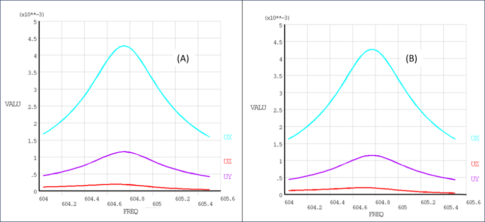
The analysis results are shown in the following figures. The analysis results of the multistage LP MSUP harmonic analysis match those of the multistage LP harmonic analysis. The similarity of these results to those from the reference full 360° harmonic analysis verifies the accuracy of the more efficient multistage cyclic symmetry approach.
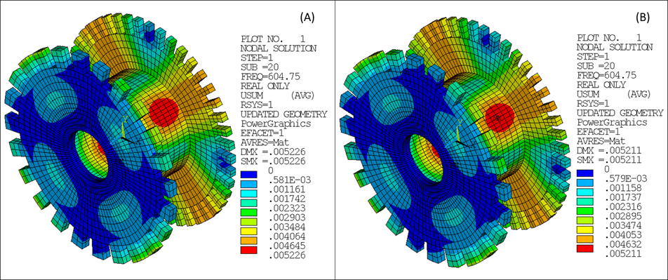
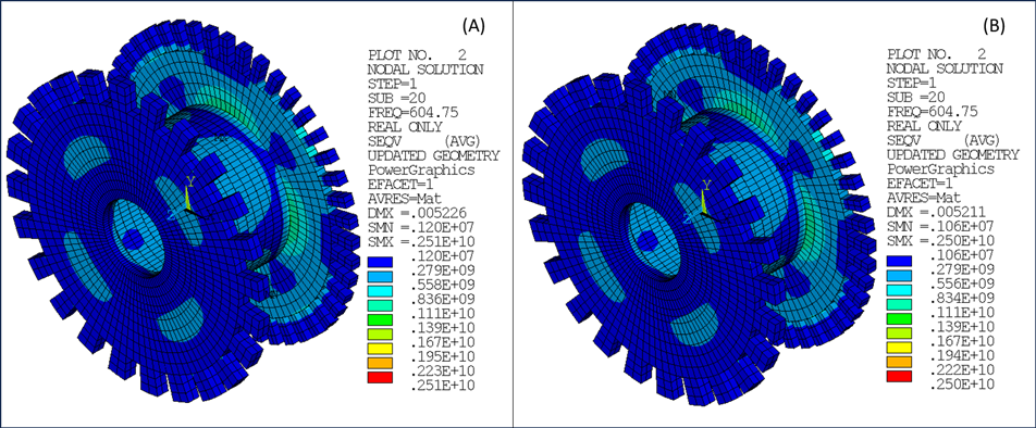
Figure 7.37: Stage 1 Displacement Frequency Response – Sector 1 for Multistage MSUP (A) and Reference Full 360° (B)
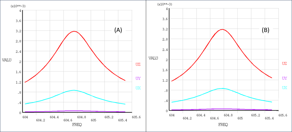
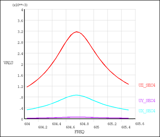
Figure 7.39: Stage 2 Displacement Frequency Response – Sector 1 for Multistage (A) and Reference Full 360° (B)