


INTER195
3D 8-Node
Gasket
INTER195 Element Description
INTER195 is a 3D 8-node linear interface element. When used with 3D linear structural elements (SOLID185, SOLSH190, and SOLID285), the element simulates gasket joints (KEYOPT(2) = 0 or 1). It is defined by eight nodes having three degrees of freedom at each node: translations in the nodal x, y, and z directions.
INTER195 is also suitable for modeling thin-solid structures with linear elastic materials (KEYOPT(2) = 2 or 3) or nonlinear von Mises plasticity (KEYOPT(2)=2). Element behavior through-the-thickness is assumed to be uniform. To properly capture the bending stiffness of a thin-solid structure, consider using standard structural solid elements (such as SOLID185 and SOLSH190).
For more information about this element, see Gasket Material and INTER195 in the Mechanical APDL Theory Reference.
Also see Gasket Joints Simulation.

INTER195 Input Data
The element geometry, node locations, connectivity, and the nodal coordinate system are shown in Figure 195.1: INTER195 Geometry. The element geometry is defined by 8 nodes, which form bottom and top surfaces of the element. The bottom surface is defined by nodes, I, J, K, L; and the top surface is defined by nodes, M, N, O, P. As shown, the element connectivity is defined as I, J, K, L, M, N, O, P.
Temperatures can be input as element body loads at the nodes. The node I temperature T(I), defaults to TUNIF. If all other temperatures are unspecified, they default to T(I). For any other input pattern, unspecified temperatures default to TUNIF.
Gasket Joint Behavior (KEYOPT(2) = 0 or 1)
The element is capable of both through-the-thickness and transverse-shear deformations (KEYOPT(2) = 1) by default. For through-the-thickness deformation only, set KEYOPT(2) = 0.
Including transverse-shear stiffness is generally required when the interfaces between the gasket and the mating parts are modeled as sliding contact; however, if the interfaces are modeled with a matching mesh method (that is, with coincident nodes), Ansys, Inc. recommends using through-thickness deformation only (KEYOPT(2) = 0) to avoid unnecessary in-plane interaction between the gasket and the mating parts.
Thin-Solid Element Behavior (KEYOPT(2) = 2 or 3)
To include both membrane and transverse stiffnesses, set KEYOPT(2) = 2. To account for transverse stiffness (thickness normal and transverse shear) only, set KEYOPT(2) = 3.
Because the element behaviors through-the-thickness are assumed to be uniform, the program uses a reduced-integration scheme (one integration point though the thickness).
If the element is not adequately constrained via either matching nodes or bonded contact with other mating parts, include a small stabilization stiffness to suppress the hourglass modes resulting from the reduced-integration rule. The stable stiffness can be added by specifying a positive stiffness scaling factor HGSTIF via the third real constant (C3). The stable stiffness is equal to HGSTIF*K, where K is the representative native stiffness of the thin-solid.
Only the linear elastic material properties, and standard stress and strain outputs, are supported by the thin-solid option without membrane stiffness (KEYOPT(2) = 3). Additionally, nonlinear material behavior based on von Mises plasticity is supported by the thin-solid behavior with membrane and transverse shear stiffness (KEYOPT(2) = 2). Corresponding plasticity related outputs, such as plastic strain, are available in this case.
By default, the element thickness is equal to the distance between the element top and bottom faces. By setting KEYOPT(7) = 1, you can provide a user-defined element thickness THKE via the second real constant (C2).
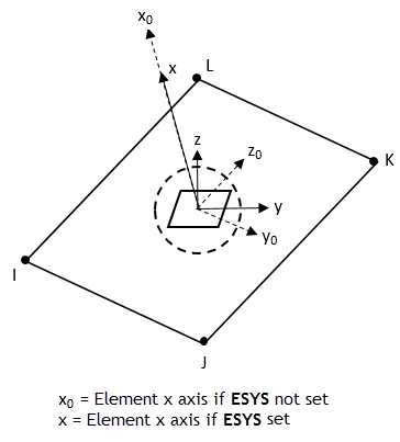
Element Orientation
You can define element orientation (ESYS) as described in Coordinate Systems. If you do so, the program compares the x axis of the local Cartesian coordinate system with the element normal direction. Proceed as follows:
If their angles are less than or equal to 45 degrees, the projection of the local y axis (onto the gasket top and bottom plane) is used as the new element y axis.
If their angles are greater than 45 degrees, check the angle between the local y axis and the element normal. If the new angle is within 45 degrees, use the projection of the local z axis (onto the gasket top and bottom plane) as the new element y axis.
If the angle between the local y axis and the element normal is still greater than 45 degree, check the angle between the local z axis and the element normal. If the new angle is within 45 degrees, use the projection of the local x axis (onto the gasket top and bottom plane) as the new element y axis.
The new element z axis is obtained by the cross product of the element normal and the new element y axis according to the right-hand rule.
INTER195 Input Summary
- Nodes
I, J, K, L, M, N, O, P
- Degrees of Freedom
UX, UY, UZ
- Real Constants
C1: Not used.
C2: THKE -- Element thickness. Effective when KEYOPT(7) = 1.
C3: HGSTF -- Hourglass stiffness scaling factor. Any positive number is valid. Default = 1e-8. If set to ≤ 0, the value resets to default. Effective when KEYOPT(2) = 2 or 3.
- Material Properties
TB command: Gasket material (KEYOPT(2) = 0 or 1).
TBcommand: See Element Support for Material Models for this element with KEYOPT(2) = 2.
TB command: Linear elastic material (KEYOPT(2) = 2 or 3).
MP command: BETD, ALPX (or CTEX or THSX), DMPR, DMPS.
MP command: EX, EY, EZ, NUXY, NUYZ, NUXZ, GXY, GXZ, GYZ (KEYOPT(2) = 2 or 3).
- Body Loads
- Temperatures --
T(I), T(J), T(K), T(L), T(M), T(N), T(O), T(P).
- Special Features
- KEYOPT(2)
Element behavior:
- 0 --
Gasket option: through-the-thickness deformation only.
- 1 --
Gasket option: through-the-thickness and transverse-shear deformation (default).
- 2 --
Thin-solid option: through-the-thickness, in-plane membrane, and transverse-shear deformation (six stress components).
- 3 --
Thin-solid option: through-the-thickness and transverse-shear deformation (three stress components).
- KEYOPT(7)
Element thickness:
- 0 --
Distance between the element top and bottom surfaces (default).
- 1 --
Defined via a real constant.
- KEYOPT(8)
Element component quantity output:
- 0 --
Output gasket quantities (GKD, GKS, GKI, and GKTH) (default). Valid for gasket option only.
- 1 --
Output standard stresses and strains (including S, EPEL, and EPTH). Valid for gasket or thin-solid option.
INTER195 Output Data
The solution output associated with the element is in two forms:
Nodal items such as nodal displacements are included in the overall nodal solution.
Element items such as stresses and closures are element outputs as shown in Table 195.1: INTER195 Element Output Definitions.
The output directions for element items are parallel to the local element coordinate system based on the element midplane as illustrated in Figure 195.3: INTER195 Stress Output. See Gasket Material in the Mechanical APDL Theory Reference for details.
A general description of solution output is given in Solution Output. See the Basic Analysis Guide for ways to review results.
The Element Output Definitions table uses the following notation:
A colon (:) in the Name column indicates that the item can be accessed by the Component Name method (ESOL). The O column indicates the availability of the items in the file Jobname.out. The R column indicates the availability of the items in the results file.
In either the O or R columns, “Y” indicates that the item is always available, a number refers to a table footnote that describes when the item is conditionally available, and “-” indicates that the item is not available.
Table 195.1: INTER195 Element Output Definitions
| Name | Definition | O | R |
|---|---|---|---|
| EL | Element number | - | Y |
| NODES | Node connectivity - I, J, K, L, M, N, O, P | - | Y |
| MAT | Material number | - | Y |
| TEMP | Temperatures T(I), T(J), T(K), T(L), T(M), T(N), T(O), T(P) | - | Y |
| GKS:X, (XY, XZ) |
X - Normal stress (also gasket pressure) XY, XZ - Transverse shear stress | 1 | 1 |
| GKD:X, (XY, XZ) |
X - Total closure XY, XZ - Relative transverse-shear deformation ( | 1 | 1 |
| GKDI:X, (XY, XZ) | Total inelastic closure | 1 | 1 |
| GKTH:X, (XY, XZ) | Thermal closure | 1 | 1 |
| S:X, Y, Z, XY, XZ, YZ | Stresses | 4 | 2, 4 |
| S:1, 2, 3 | Principal stresses | - | 2, 4 |
| S:INT | Stress intensity | - | 2, 4 |
| S:EQV | Equivalent stress | - | 2, 4 |
| EPEL:X, Y, Z, XY, XZ, YZ | Elastic strains | 4 | 2, 4 |
| EPEL:EQV | Equivalent elastic strain | - | 2, 4 |
| EPTH:X, Y, Z, XY, XZ, YZ | Thermal strains | - | 2, 4 |
| EPTH:EQV | Equivalent thermal strain | - | 2, 4 |
| EPPL:X, Y, Z, XY, XZ, YZ | Plastic strains | 5 | 5 |
| EPPL:EQV | Equivalent plastic strain | - | 5 |
| EPTO:X, Y, Z, XY, XZ, YZ | Total mechanical strains (EPEL + EPPL) | 5 | - |
| NL:SEPL | Plastic yield stress | - | 5 |
| NL:EPEQ | Accumulated equivalent plastic strain | 5 | 5 |
| NL:SRAT | Plastic yielding (1 = actively yielding, 0 = not yielding) | 5 | 5 |
| NL:PLWK | Plastic work/volume | 5 | 5 |
| NL:HPRES | Hydrostatic pressure | 5 | 5 |
| SEND:ELASTIC | Strain energy densities | - | 3 |
| SEND:ELASTIC, PLASTIC, ENTO | Strain energy densities | - | 5 |


Output available if Gasket option is used (KEYOPT(2) = 0 or 1).
If Gasket option is used (KEYOPT(2) = 0 or 1), then set KEYOPT(8) = 1 to save these results to the .rst file.
Output available if thin-solid option used (KEYOPT(2) = 2 or 3).
Nonlinear solution, output only if the element has nonlinear material (requires thin-solid option with membrane and transverse shear stiffness KEYOPT(2) = 2).
INTER195 Assumptions and Restrictions
This element is not supported for initial stress.
Pressure as a type of surface load on element faces is not supported by this element.
Mass inertia summary does not reflect user-defined element thickness (THKE).
For a user-defined thickness (THKE) specified via KEYOPT(7) = 1, the program determines the transverse-shear strains by multiplying those on the original geometry times a ratio of the original element thickness to THKE (independent of element shear-deformation patterns).