
Applying Wiring/Crosstalk Rules
To change EMI Scanner Wiring/Crosstalk rules:
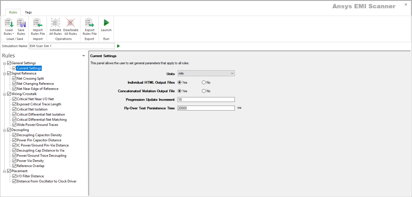
- Launch EMI Scanner.
The EMI Scanner window appears, on the Rules tab.
- From the Rules pane, select one of the six subcategories under Wiring/Crosstalk:
- Critical Net Near I/O Net – displays Critical Net Near I/O Net rule configuration.

This rule states that critical nets may not be routed within a specified distance from an I/O net.
From here, you can set the following:
- Rule State – toggles Critical Net Near I/O Net rules on or off.
- Min Required Distance Between Critical Net and I/O Net – specifies the minimum distance between all critical nets and all I/O nets.
- I/O Nets Class to Include – specifies the type(s) of I/O Nets to include. Select one, or Ctrl+click to select multiple types. See Technical Note.
- Sort by Column – specifies the column by which results are sorted.
- Log File State – determines whether EMI Scanner creates a log file with additional details (intended for use in debugging).
- Weighting Factor – specifies the weighting factor (0<factor<=1) that is applied to violations of this rule when assigning a rank. A violation's rank is its own "degree of badness" multiplied by the weighting factor. See Exporting EMI Scanner Results and Analyzing EMI Scanner Results Using iQ-Harmony.
- Min I/O Net Segment Length to Check – specifies the smallest I/O net segment length to check for violations. EMI Scanner ignores All I/O net segments smaller than this length.
- Min Critical Net Segment Length to Check – specifies the smallest critical net segment length to check for violations. EMI Scanner ignores all critical net segments smaller than this length.
- Check Nets on Different Layers – determines whether to check the distance between I/O nets and critical nets when these nets are on different layers and between the same pair of planes.
- Check I/O Components – determines whether any I/O component that is within the specified distance from a critical net will cause a violation.
- Check Nets that are Both I/O and Critical – determines whether nets labeled as both critical and I/O should be checked for distance from other I/O nets.
- Ignore Violations If Net Approaches Edge at 90 Degrees +/- – EMI scanner ignores edge connectors that approach the edge of the reference plane or board at a 90 degree angle. This option specifies a tolerance that allows the approach to be slightly off a perfect 90 degrees.
- Suppress Multiple Violations for Same Net-to-Net Ratio – determines whether to suppress multiple violation reporting when multiple segments on a critical net infringe on the same I/O net.
- Report Violation Only Once per I/O Component – reduces run time by checking only for violations between critical nets and I/O components when no other violation has been found for an I/O component.
- Exposed Critical Trace Length – displays Length of Exposed Critical Traces rule configuration.

This rule states that all critical nets must be buried between solid planes.
From here, you can set the following:
- Rule State – toggles Exposed Critical Trace Length rules on or off.
- Maximum Exposed Critical Net Segment Length – specifies the maximum critical net segment length allowed on external (exposed) layers.
- Total Maximum Exposed Critical Net Length – specifies the total maximum critical net length allowed on external (exposed) layers (e.g., multiple segments on a critical net may be exposed, but short enough not to cause a violation individually).
- Sort by Column – specifies the column by which results are sorted.
- Log File State – determines whether EMI Scanner creates a log file with additional details (intended for use in debugging).
- Weighting Factor – specifies the weighting factor (0<factor<=1) that is applied to violations of this rule when assigning a rank. A violation's rank is its own "degree of badness" multiplied by the weighting factor. See Exporting EMI Scanner Results and Analyzing EMI Scanner Results Using iQ-Harmony.
- Net Choice – specifies the nets to include in this rule analysis. Select one, or Ctrl+click to select multiple nets.
- Critical Net Isolation – displays Critical Net Isolation (Single-Ended Nets) rule configuration.

This rule states that all critical nets must have empty tracks or a "ground-guard" trace on either side of the critical net.
From here, you can set the following:
- Rule State – toggles Critical Net Isolation rules on or off.
- Vacant Track Isolation Allowed – specifies whether vacant tracks (empty space) may be used in place of ground-guard traces.
- Minimum Isolation Distance Required – selects the minimum edge-to-edge distance required between critical nets and all other nets before EMI Scanner reports a violation. Used in coordination with Vacant Track Isolation Allowed.
- Sort by Column – specifies the column by which results are sorted.
- Log File State – determines whether EMI Scanner creates a log file with additional details (intended for use in debugging).
- Weighting Factor – specifies the weighting factor (0<factor<=1) that is applied to violations of this rule when assigning a rank. A violation's rank is its own "degree of badness" multiplied by the weighting factor. See Exporting EMI Scanner Results and Analyzing EMI Scanner Results Using iQ-Harmony.
- Minimum Critical Net Segment Length – specifies the minimum critical net segment length before EMI Scanner will report a violation. Segments shorter than this length are ignored.
- Max Distance Between Vias on Ground-Guard Traces – specifies the maximum distance between vias on ground-guard traces.
- Ignore Violations If Approach Angle is 90 Degrees +/- – EMI scanner ignores edge connectors that approach the edge of the reference plane or board at a 90 degree angle. This option specifies a tolerance that allows the approach to be slightly off a perfect 90 degrees.
- Critical Differential Net Isolation – displays Critical Net Isolation (Differential Nets) rule configuration.

This rule states that all differential critical nets must have empty tracks or a "ground-guard" trace on either side of the differential pair.
From here, you can set the following:
- Rule State – toggles Critical Differential Net Isolation rules on or off.
- Vacant Track Isolation Allowed – determines whether vacant tracks (empty space) may be used in place of ground-guard traces.
- Minimum Isolation Distance Required – when Vacant Track Isolation Allowed is selected, this setting determines the minimum edge-to-edge distance required between critical nets and all other nets before EMI Scanner reports a violation.
- Sort by Column – specifies the column by which results are sorted.
- Log File State – determines whether EMI Scanner creates a log file with additional details (intended for use in debugging).
- Weighting Factor – specifies the weighting factor (0<factor<=1) that is applied to violations of this rule when assigning a rank. A violation's rank is its own "degree of badness" multiplied by the weighting factor. See Exporting EMI Scanner Results and Analyzing EMI Scanner Results Using iQ-Harmony.
- Max Distance Between Complementary Nets – sets the maximum spacing between a pair of critical nets (creating a critical differential pair).
- Minimum Critical Net Segment Length – allows you to ignore short critical net segments by specifying the minimum critical net segment length before EMI Scanner will report a violation.
- Max Distance between Vias on Ground-Guard Traces – specifies the maximum distance between vias on ground-guard traces.
- Ignore Violations If Approach Angle is 90 Degrees +/- – EMI scanner ignores edge connectors that approach the edge of the reference plane or board at a 90 degree angle. This option specifies a tolerance that allows the approach to be slightly off a perfect 90 degrees.
- Critical Differential Net Matching – displays Critical Differential Net Length Matching and Spacing rule configuration.

This rule states that all critical nets must be routed within a specified distance of each other, and that the length of the differential pair must match within a specified amount.
From here, you can set the following:
- Rule State – toggles Critical Differential Net Matching rules on or off.
- Max Distance Between Complementary Nets – sets the maximum spacing between a pair of critical nets (creating a critical differential pair).
- Maximum Length Mismatch – specifies the maximum difference in length between a critical differential pair of nets.
- Sort by Column – specifies the column by which results are sorted.
- Log File State – determines whether EMI Scanner creates a log file with additional details (intended for use in debugging).
- Weighting Factor – specifies the weighting factor (0<factor<=1) that is applied to violations of this rule when assigning a rank. A violation's rank is its own "degree of badness" multiplied by the weighting factor. See Exporting EMI Scanner Results and Analyzing EMI Scanner Results Using iQ-Harmony.
- Min Critical Net Segment Length – allows you to ignore short critical net segments by specifying the minimum critical net segment length before EMI Scanner will report a violation.
- Wide Power/Ground Traces – displays Wide Power/Ground Traces rule configuration.
- Rule State – toggles Wide Power/Ground Traces rules on or off.
- Min Power/Ground Trace Width – sets a minimum width limit for all power/ground traces (except grounded guard traces).
- Min Power/Ground Trace Length – specifies the smallest trace length to check for violations. EMI Scanner ignores traces smaller than this length.
- Sort by Column – specifies the column by which results are sorted.
- Log File State – determines whether EMI Scanner creates a log file with additional details (intended for use in debugging).
- Weighting Factor – specifies the weighting factor (0<factor<=1) that is applied to violations of this rule when assigning a rank. A violation's rank is its own "degree of badness" multiplied by the weighting factor. See Exporting EMI Scanner Results and Analyzing EMI Scanner Results Using iQ-Harmony.

This rule states that all power and ground traces longer than a specified distance must be wider than a specified amount.
From here, you can set the following:
- Critical Net Near I/O Net – displays Critical Net Near I/O Net rule configuration.
- Rules are automatically saved for the current EMI scan. To save them for a future scan, click Save Rules.
- You can display a description of a rule parameter at any time by hovering the cursor over it.
- Units of measure are set in General Settings.