
Applying Decoupling Rules
To change EMI Scanner Decoupling rules:
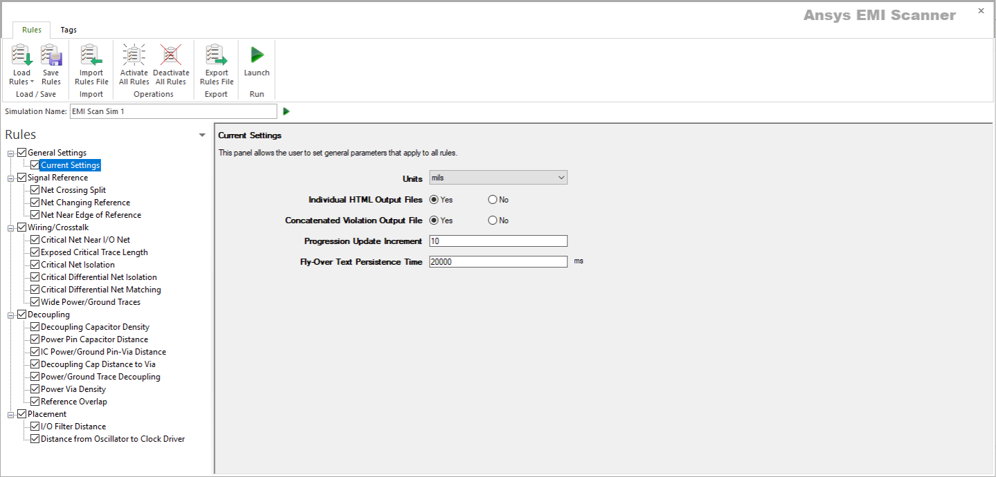
- Launch EMI Scanner.
The EMI Scanner window appears, on the Rules tab.
- From the Rules pane, select one of the seven subcategories under Decoupling:
- Decoupling Capacitor Density – displays Decoupling Capacitor Density rule configuration.

This rule states that decoupling capacitors must be placed between all adjacent plane pairs within a specified grid density.
From here, you can set the following:
- Rule State – toggles Decoupling Capacitor Density rules on or off.
- Check Only for Pwr-to-Gnd Plane Decoupling – sets whether to ignore plane-to-plane decoupling and check only for decoupling capacitors between power and ground planes.
- Grid Size (X Direction) – specifies the size of the grid used to check for decoupling capacitors. Used in conjunction with Grid Size (Y Direction).
- Grid Size (Y Direction) – specifies the size of the grid used to check for decoupling capacitors. Used in conjunction with Grid Size (X Direction).
- Number of Decoupling Caps Required within Each Grid – specifies the number of decoupling capacitors connecting between planes that are required within each grid location.
- Number of Vias Required within Each Grid – specifies the number of vias connecting between planes that are required within each grid location. You must select Allow Via Connection for Same Net Name to use this option.
- Sort by Column – specifies the column by which results are sorted.
- Log File State – determines whether EMI Scanner creates a log file with additional details (intended for use in debugging).
- Weighting Factor – specifies the weighting factor (0<factor<=1) that is applied to violations of this rule when assigning a rank. A violation's rank is its own "degree of badness" multiplied by the weighting factor. See Exporting EMI Scanner Results and Analyzing EMI Scanner Results Using iQ-Harmony.
- Allow Via Connection for Same Net Name – determines whether EMI Scanner allows a via in place of a decoupling capacitor when the two planes are the same net name.
- Include Power/Ground Islands on Signal Layers – specifies whether to check for decoupling on power/ground islands.
- Check Only When Grid on Board by at Least – specifies the percentage of a grid that must be on the board in order for it to be checked.
- Ignore Violations from Pwr/Gnd Nets with Same Name – determines that only one plane of a given name is checked for violations (e.g., if two planes are "gnd" and a violation occurs between gnd and another layer, only one violation is reported).
- Require One Capacitor Pin to be Inside Grid – changes how EMI Scanner determines whether a component is inside or outside the grid. See Technical Note.
- Require ALL Capacitor Pins to be Inside Grid – changes how EMI Scanner determines whether a component is inside or outside the grid. See Technical Note.
- Layer Choice – specifies the layers to include in this rule analysis.
- Power Pin Capacitor Distance – displays Decoupling Capacitor Distance from IC Power Pin rule configuration.

This rule states that a decoupling capacitor must be connected between the power and ground-reference planes and be placed within a specified distance of each IC power pin.
From here, you can set the following:
- Rule State – toggles Power Pin Capacitor Distance rules on or off.
- Max Distance between Decoupling Cap and IC Power Pin – specifies the maximum distance between an IC power pin and its decoupling capacitor.
- Sort by Column – specifies the column by which results are sorted.
- Log File State – determines whether EMI Scanner creates a log file with additional details (intended for use in debugging).
- Weighting Factor – specifies the weighting factor (0<factor<=1) that is applied to violations of this rule when assigning a rank. A violation's rank is its own "degree of badness" multiplied by the weighting factor. See Exporting EMI Scanner Results and Analyzing EMI Scanner Results Using iQ-Harmony.
- Maximum Search Distance for Cap – specifies a maximum search distance for a capacitor. A larger search box increases the chances of EMI Scanner finding capacitors, but can slow processing time.
- Allow Capacitors on Both Sides of Board – specifies whether to include capacitors on both sides of the board.
- Require Only One Cap Pin to be Within Specified Distance – changes how EMI Scanner determines whether a component is inside or outside the grid. See Technical Note.
- Require ALL Cap Pins to be within Specified Distance – changes how EMI Scanner determines whether a component is inside or outside the grid. See Technical Note.
- ICs to Check – selects the types of components to include in this rule analysis.
- IC Power/Ground Pin-Via Distance – displays IC Power/Ground-Reference Pin Distance to Via rule configuration.

This rule states that the trace connecting the IC power/ground reference pin to its associated via to the power/ground-reference plane must be no longer than a specified distance.
From here, you can set the following:
- Rule State – toggles IC Power/Ground Pin-Via Distance rules on or off.
- Maximum Distance between IC Pin and Via – specifies the maximum distance between the center of the IC power or ground-reference pin and the center of the via to the power or ground-reference plane.
- Sort by Column – specifies the column by which results are sorted.
- Log File State – determines whether EMI Scanner creates a log file with additional details (intended for use in debugging).
- Weighting Factor – specifies the weighting factor (0<factor<=1) that is applied to violations of this rule when assigning a rank. A violation's rank is its own "degree of badness" multiplied by the weighting factor. See Exporting EMI Scanner Results and Analyzing EMI Scanner Results Using iQ-Harmony.
- Maximum Search Distance for Via – specifies a maximum search distance for a via when a violation is found. This allows you to spot vias that are barely outside the original requirement and therefore not serious violations.
- Check Power/Ground Pins Without Plane – checks the distance between the IC power/ground pin and its via when the power/ground plane has not been completed yet.
- Verify Via Connected to Appropriate Plane – selecting 'no' speeds up EMI Scanner by not verifying that the via connects to an appropriate plane (shape).
- Decoupling Cap Distance to Via – displays Decoupling Capacitor Distance to Via rule configuration.

This rule states that the trace connecting a decoupling capacitor to its associated via to the power/ground-reference plane must be no longer than the specified distance.
From here, you can set the following:
- Rule State – toggles Decoupling Cap Distance to Via rules on or off.
- Maximum Distance Between Capacitor and Via – specifies the maximum distance between the capacitor pin and the center of the via to the power or ground-reference plane.
- Sort by Column – specifies the column by which results are sorted.
- Log File State – determines whether EMI Scanner creates a log file with additional details (intended for use in debugging).
- Weighting Factor – specifies the weighting factor (0<factor<=1) that is applied to violations of this rule when assigning a rank. A violation's rank is its own "degree of badness" multiplied by the weighting factor. See Exporting EMI Scanner Results and Analyzing EMI Scanner Results Using iQ-Harmony.
- Maximum Search Distance for Via – specifies a maximum search distance for a via when a violation is found. This allows you to spot vias that are barely outside the original requirement and therefore not serious violations.
- Verify Via Connected to Appropriate Plane – selecting 'no' speeds up EMI Scanner by not verifying that the via connects to an appropriate plane (shape).
- Power/Ground Trace Decoupling – displays Power/Ground-Reference Trace Decoupling rule configuration.

This rule states that all power and ground-reference traces longer than a specified length must have a decoupling capacitor within a specified distance of the IC power pin.
From here, you can set the following:
- Rule State – toggles Power/Ground Trace Decoupling rules on or off.
- Maximum Ignorable Power/Ground Trace Length – specifies the maximum power/ground trace length that may be ignored. All traces longer than this length must meet this rule's requirement.
- Max Distance between Cap and IC Power Pin – specifies the maximum distance between the capacitor pin and the power or ground-reference pin.
- Sort by Column – specifies the column by which results are sorted.
- Log File State – determines whether EMI Scanner creates a log file with additional details (intended for use in debugging).
- Weighting Factor – specifies the weighting factor (0<factor<=1) that is applied to violations of this rule when assigning a rank. A violation's rank is its own "degree of badness" multiplied by the weighting factor. See Exporting EMI Scanner Results and Analyzing EMI Scanner Results Using iQ-Harmony.
- Net Choice – specifies the nets to include in this rule analysis. Select one, or Ctrl+click to select multiple nets.
- Power/Via Density – displays Power Via Density rule configuration.

This rule checks for power planes that do not have enough adjacent layer via connections.
From here, you can set the following:
- Rule State – toggles Power Via Density rules on or off.
- Minimum Number of Vias – sets the minimum number of vias required to connect adjacent power planes.
- Use Grid – toggles the use of a grid on or off.
- Grid Size (X Direction/Y Direction) – when Use Grid is enabled, these fields specify the size of the grid.
- Number of Vias Required within Each Grid – when Use Grid is enabled, specifies the number of vias required within each grid.
- Check Only When Grid on Board by at Least – specifies the percentage of the grid that must be on the board for analysis to occur.
- Sort by Column – specifies the column by which results are sorted.
- Log File State – determines whether EMI Scanner creates a log file with additional details (intended for use in debugging).
- Weighting Factor – specifies the weighting factor (0<factor<=1) that is applied to violations of this rule when assigning a rank. A violation's rank is its own "degree of badness" multiplied by the weighting factor. See Exporting EMI Scanner Results and Analyzing EMI Scanner Results Using iQ-Harmony.
- Reference Overlap – displays Disparate Reference Overlap rule configuration.

The Disparate Reference Overlap rule checks for overlapping reference planes from different domains.
From here, you can set the following:
- Rule State – toggles Disparate Reference Overlap on or off.
- Maximum Total Overlap Area – specifies the maximum overlap area that is acceptable. Overlap over this maximum will report a violation.
- Nets to Include in Reference Group A – selects a net type.
- Nets to Include in Reference Group B – selects a net type.
- Sort by Column – specifies the column by which results are sorted.
- Log File State – determines whether EMI Scanner creates a log file with additional details (intended for use in debugging).
- Weighting Factor – specifies the weighting factor (0<factor<=1) that is applied to violations of this rule when assigning a rank. A violation's rank is its own "degree of badness" multiplied by the weighting factor. See Exporting EMI Scanner Results and Analyzing EMI Scanner Results Using iQ-Harmony.
- Decoupling Capacitor Density – displays Decoupling Capacitor Density rule configuration.
- Rules are automatically saved for the current EMI scan. To save them for a future scan, click Save Rules.
- You can display a description of a rule parameter at any time by hovering the cursor over it.
- Units of measure are set in General Settings.